Download
1 / 15
150 likes | 181 Vues
This study explores logic simulation with bounded gate delays to enhance existing min-max delay simulation, focusing on process variation for quality improvement in digital circuits. Investigate and improve the efficiency of delay testing using a new ambiguity interval approach.

E N D
Delay Test Quality Evaluation Using Bounded Gate Delays Soumitra Bose Intel Corporation, Design Technology, Folsom, CA 95630 Vishwani D. Agrawal Auburn University, Dept. of ECE, Auburn, AL 36849 VTS'07
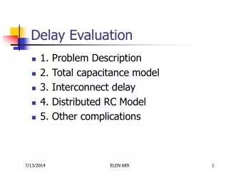
Problem Statement • Investigate logic simulation with bounded delays specified for process variation. • Improve upon existing min-max delay simulation. VTS'07
Some Previous Work • J. W. Bierbauer, J. A. Eiseman, F. A. Fazal, and J. J. Kulikowski, “System Simulation with MIDAS,” AT&T Tech. Jour., vol. 70, no. 1, pp. 36-51, January 1991. • A. K. Pramanick and S. M. Reddy, “On the Fault Coverage of Gate Delay Fault Detecting Tests,” IEEE Trans. CAD, vol. 16, no. 1, pp. 78-94, January 1997. • S. Chakraborty, D. L. Dill, and K. Y. Yun, “Min-max Timing Analysis and Application to Asynchronous Circuits,” Proc. IEEE, vol. 87, no. 2, pp. 332-346, February 1999. VTS'07
Digital Circuit Timing and Delay Test Input Signal changes Output Observation instant Transient region Comb. logic Inputs Synchronized with clock Outputs time Clock period VTS'07
C17: Zero-Delay Simulation Untested path Non-robustly tested path 11 11 CK 00 11 Robustly tested path VTS'07
C17: Min-Max Delay Simulation Nominal delay = 3.5 (min,max) delay = 3,4 11 6 8 9 12 3 4 3,4 3,4 0 6 8 3,4 0 9 12 3 4 3,4 3,4 11 11 3,4 1/fmax 00 Performance range VTS'07
Min-Max Delay Simulation Range of operation fmax 11 4 7 4 6 4,6 1,1 0 1 4 1,4 0,0 3 4 2,2 1,4 3 6 1 4 VTS'07
Improving Min-Max Delay Simulation fmax 11 4 5 7 4 6 4,6 1,1 Fall at time x 1 x 4 x 0 1,4 0,0 3 4 2,2 Ghost hazard 1,4 x+2 6 Output rises at least 2 units after the later of inputs falls. 1 4 VTS'07
A New Idea in Simulation • Generate ambiguity intervals at fanouts. • Propagate ambiguity interval lists through gates – similar to fault lists in concurrent fault simulation. • Use ambiguity interval correlations among reconverging signals to improve hazard analysis. VTS'07
Sketch of New Simulation Algorithm • An event generated at a fanout node generates an ambiguity list entry consisting of: • Originating fanout signal name • Ambiguity interval, initially (0,0) • Gate evaluation: Examine multiple events with same originating signal • Overlapping ambiguity periods: analyze interference • Non-overlapping ambiguity periods: propagate independently • Ambiguity list propagation: If an event propagates through a gate, the corresponding ambiguity list is propagated to output with ambiguity interval adjusted for (min,max) gate delays. VTS'07
Benchmark Circuits • Zero-delay path simulation • 5-20 thousand random vectors • Delay model: • Nominal delay of each gate = 3.5 units • Min-max delay (3, 4), i.e., ±14% variation • fmax = 1/(nominal delay of critical path) • Min-max delay simulation: re-determine fmax VTS'07
Path Delay Coverage VTS'07
Critical Path Delay and fmax Zero-delay path simulation: Primary output event on non-robust critical path Primary input event Delay range time 1/fmax Nominal delay of critical path Min-max delay simulation: Min-max performance range time 1/f’max Percent change in fmax = 100 (fmax – f’max) / fmax VTS'07
Determination of fmax VTS'07
Conclusion • Delay independent simulation becomes too pessimistic when we want the result to remain correct in the presence of large process variations. • Conventional min-max delay (bounded delay) simulation produces extra ambiguity periods (hazards) because correlations between signals are neglected. • Pessimism (ambiguity, hazards) is reduced when correlation among reconverging signals is considered. • This paper presents an improved min-max delay (bounded delay) simulation algorithm. VTS'07