Download
1 / 3
30 likes | 108 Vues
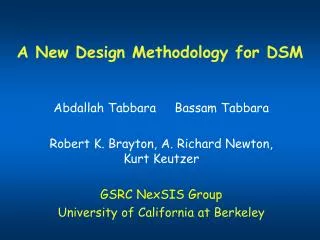
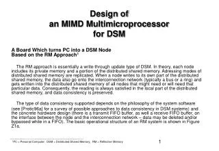
A Board Which turns PC into a DSM Node Based on the RM Approach 1

E N D
A Board Which turns PC into a DSM Node Based on the RM Approach1 The RM approach is essentially a write-through update type of DSM. In theory, each node includes its private memory and a portion of the distributed shared memory. Adressing modes of distributed shared memory are replicated. When a node writes to its own part of the distributedshared memory, the data also go onto the interconnection network (typically a bus or a ring) and gets written into the distributed shared memory of all nodes that might need or will need that particular data. Consequently, the reading is always satisfied in the local part of the distributed shared memory, and data consistency is preserved. The type of data consistency supported depends on the philosophy of the system software (see [Protic96a] for a survey of possible approaches to data consistency in DSM systems) and the concrete hardware design (there is a transmit FIFO buffer, as well a receive FIFO buffer, on the interface between the node and the interconnection network – data may be deleted and/or bypassed while in a FIFO). The basic operational structure of an RM system is shown in Figure Z1a. Design ofan MIMD Multimicroprocessorfor DSM 1PC = Personal Computer; DSM = Distributed Shared Memory; RM = Reflective Memory
Figure Z1: Basic Operational Structure Legend: DMA – Direct Memory Access TMI – Transition Module Interface Comment: An important characteristic of this approach is that it can be implemented using off-the-shelf and FPG components only.