Download
1 / 22
230 likes | 424 Vues
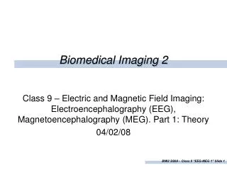
Bioengineering 280A Principles of Biomedical Imaging Fall Quarter 2005 MRI Lecture 5. Slice Selection. RF. Slice select gradient. G z (t). Slice refocusing gradient. G x (t). G y (t). Gradient Echo. RF. Slice select gradient. G z (t). Slice refocusing gradient. G x (t). G y (t).

E N D
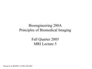
Bioengineering 280APrinciples of Biomedical ImagingFall Quarter 2005MRI Lecture 5
Slice Selection RF Slice select gradient Gz(t) Slice refocusing gradient Gx(t) Gy(t)
Gradient Echo RF Slice select gradient Gz(t) Slice refocusing gradient Gx(t) Gy(t) Spins all in phase at kx=0 ADC
Static Inhomogeneities In the ideal situation, the static magnetic field is totally uniform and the reconstructed object is determined solely by the applied gradient fields. In reality, the magnet is not perfect and will not be totally uniform. Part of this can be addressed by additional coils called “shim” coils, and the process of making the field more uniform is called “shimming”. In the old days this was done manually, but modern magnets can do this automatically. In addition to magnet imperfections, most biological samples are inhomogeneous and this will lead to inhomogeneity in the field. This is because, each tissue has different magnetic properties and will distort the field.
Static Inhomogeneities The spatial nonuniformity in the field can be modeled by adding an additional term to our signal equation. The effect of this nonuniformity is to cause the spins to dephase with time and thus for the signal to decrease more rapidly. To first order this can be modeled as an additional decay term of the form
T2* decay The overall decay has the form. where Due to random motions of spins. Not reversible. Due to static inhomogeneities. Reversible with a spin-echo sequence.
T2* decay Gradient echo sequences exhibit T2* decay. RF Slice select gradient Gz(t) Slice refocusing gradient Gx(t) Gradient echo has exp(-TE/T2*)weighting Gy(t) ADC TE = echo time
Spin Echo Discovered by Erwin Hahn in 1950. 180º The spin-echo can refocus the dephasing of spins due to static inhomogeneities. However, there will still be T2 dephasing due to random motion of spins. There is nothing that nuclear spins will not do for you, as long as you treat them as human beings. Erwin Hahn Image: Larry Frank
Spin Echo 180º Phase at time Phase after 180 pulse Phase at time 2 Image: Larry Frank
Spin Echo Pulse Sequence 90 180 RF Gz(t) Gx(t) Gy(t) ADC TE = echo time
Image Contrast Different tissues exhibit different relaxation rates, T1, T2, and T2*. In addition different tissues can have different densities of protons. By adjusting the pulse sequence, we can create contrast between the tissues. The most basic way of creating contrast is adjusting the two sequence parameters: TE (echo time) and TR (repetition time).
Saturation Recovery Sequence 90 TE 90 TE 90 TR TR Gradient Echo 180 180 90 90 90 TE TR Spin Echo
T1-Weighted Scans Make TE very short compared to either T2 or T2*. The resultant image has both proton and T1 weighting.
T2-Weighted Scans Make TR very long compared to T1 and use a spin-echo pulse sequence. The resultant image has both proton and T2 weighting.
Proton Density Weighted Scans Make TR very long compared to T1 and use a very short TE. The resultant image is proton density weighted.
Example T1-weighted Density-weighted T2-weighted
FLASH sequence TE TE TR TR Gradient Echo Signal intensity is maximized at the Ernst Angle FLASH equation assumes no coherence from shot to shot. In practice this is achieved with RF spoiling.
FLASH/SPGR GE Medical Systems 2003
Inversion Recovery 180 180 180 180 90 90 TI TE TR Intensity is zero when inversion time is
Inversion Recovery GE Medical Systems 2003
Fast Spin Echo GE Medical Systems 2003
Echoplanar Imaging GE Medical Systems 2003