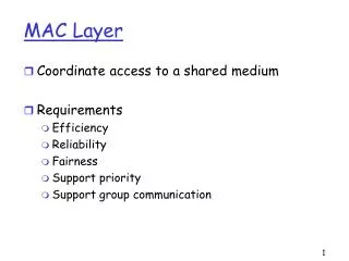
The MAC layer
The MAC layer. Jean-Yves Le Boudec Fall 2009. Contents. 1. MAC as Shared Medium 2. MAC as interconnection at small scale 3. MAC and Link layer. 1: Shared Medium Access . Why did engineers invent the MAC layer ? Share a cable (Ethernet, Token Ring, 1980s)

The MAC layer
E N D
Presentation Transcript
The MAC layer Jean-Yves Le Boudec Fall 2009 1
Contents • 1. MAC as Shared Medium • 2. MAC as interconnection at small scale • 3. MAC and Link layer 2
1: Shared Medium Access • Why did engineers invent the MAC layer ? • Share a cable (Ethernet, Token Ring, 1980s) • Use a wireless radio link (GSM, WiFi, WiMax, etc) • What is the problem ? • If several systems talk together, how can we decode ? • Solution 1: joint decoding (decode everyone) used in CDMA cellular networks – complex • Solution 2: mutual exclusion protocol • Only one system can talk at a time 3
*What is the goal of the MAC layer ? • MAC = medium access control • What does it do ? • Implement a mutual exclusion protocol • Without any central system – fully distributed • How does it work ? • there are many solutions, called: Token Passing, Aloha, CSMA, CMSA/CA, CSMA/CD, RMAC, etc • We describe here the most basic one, called CSMA/CD, used on Ethernet cables • Powerline (“homeplug MAC”) is similar (CSMA/Collision Avoidance) for transmission over home power lines • Radio links (WiFi) is similar, with a few complications – see course on mobile newtorks for a very detailed explanation 4
*CSMA/CA derives from Aloha • Aloha is the basis of all non-deterministic access methods. The Aloha protocol was originally developped for communications between islands (University of Hawaï) that use radio channels at low bit rates. • The Aloha protocol requires acknowledgements and timers. • Collisions occur when two packet transmissions overlap, and if a packet is lost, then source has to retransmit; the retransmission strategy is not specified here; many possibilities exist. We will see the one used for CSMA/CD. • There is no feedback to the source in case of collision (was too complex to implement at that time). The picture shows a radio transmission scenario; Aloha can also be used on a cable (bus). It is used nowadays in cases where simplicity is more important than performance (for example: ATM metasignalling) • The maximum utilization can be proven to be 18%. This is assuming an ideal retransmission policy that avoids unnecessary repetitions of collisions. 5
ALOHA data central host ack transmission procedure i = 1 while (i <= maxAttempts) do send packet wait for acknowledgement or timeout if ack received thenleave wait for random time increment i end do 6
CSMA improves on Aloha by requiring that stations listen before transmitting • CSMA = carrier sense multiple access • Listen before you talk: ”Carrier Sense Multiple Access“ i = 1 while (i · maxAttempts) do listen until channel idle transmit immediately wait for acknowledgement or timeout if ack received thenleave wait random time /* collision*/ increment i end do 7
CSMA avoids some collisions, but not all • Some collisions can be avoided, but not completely. This is because of propagation delays. If two or more stations may sense that the medium (= the channel) is free and start transmitting at time instants that are close enough for a collision to occur. Assume propagation time between A and B is 2 ms and that all stations are silent until time 0. At time 0, station A starts transmitting for 10 ms, at time 1 ms, station B has not received any signal from A yet, so it can start transmitting. At time 2ms, station B senses the collision but it is too late according to the protocol. • The CSMA protocol requires that stations be able to monitor whether the channel is idle or busy (no requirements to detect collisions). It is a simple improvement to Aloha, at the expense of implementing the monitoring hardware. • The effect of the CSMA protocol can be expressed in the following way. Call T the maximum propagation time from station A to any other stations; if no collision occurs during a time interval of duration T after A started transmitting, then A has seized the channel (no other station can send). • CSMA works well only if the transmission time is much larger than propagagation, namely bandwidth-delay product << frame size. • In order to avoid repeated collisions, it is required to wait for a random delay before re-transmitting. If all stations choose the random delays independently, and if the value of the delay has good chances of being larger than T, then there is a high probability that only one of the retransmitting stations seizes the channel. 8
CSMA / CD detects collisions as they occur • CSMA/CD=Carrier Sense Multiple Access / Collision Detection=Ethernet • acknowledgments replaced by CD i = 1 while (i · maxAttempts) do listen until channel is idle transmit and listen wait until (end of transmission) or (collision detected) if collision detected then stop transmitting /* after 32 bits (“jam”)*/ else wait for interframe delay leave wait random time increment i end do 9
CSMA / CD Time Diagram 1 B A • A senses idle channel, starts transmitting • shortly before T, B senses idle channel, starts transmitting 0 T 10
CSMA / CD Time Diagram 2 B A • A senses collision, continues to transmit 32 bits (“jam”) • B senses collision, continues to transmit 32 bits (”jam“) 0 T t2 11
CSMA / CD Time Diagram 3 B A • A waits random time t1 • B waits random time t2 • B senses channel idle and transmits • A senses channel busy and defers to B • A now waits until channel is idle 0 T t2 t1 12
CSMA/CD improves on CSMA by requiring that stations detect collisions and stop transmitting (after 32 bits, called jam bits, in order to ensure that all circuits properly recognize the presence of collisions). • CSMA/CD has a better performance than Aloha or CSMA • After a collision is detected, stations will re-attempt to transmit after a random time. • Acknowledgements are not necessary because absence of collision means that the frame could be transmitted (see “Minimum Frame Size“). • The interframe delay (“gap”) is 9.6 µs. It is used to avoid blind times, during which adapters are filtering typical noise at transmission ends. • The random time before retransmission is chosen in such a way that if repeated collisions occur, then this time increases exponentially. The effect is that in case of congestion (too many collisions) the access to the channel is slowed down. 13
Exponential Backoff • random time before re-transmission is given by: “AttemptNb” is the number of the re-transmission attempt that will be attempted after the random time (k=1 for the first retransmission); “random” returns an integer, uniformly distributed between the two bounds given in argument; • examples:first retransmission attempt: k = 1; r = 0 or r = slotTime second retransmission attempt (if preceding one failed): k = 2; r = 0, 1, 2 or 3 £ slotTime k = min (10, AttemptNb)r = random (0, 2k -1) £ slotTime 14
Frame sent by A is too short: collision is not visible at A but is visible at C Frame sent by A is large enough collision is visible at A A Minimum Frame Size is Necessary to Guarantee Collision Detection A C B A C B 15
Ethernet Imposes a Minimum Frame Size • Let = bandwidth – delay product + safety margin = 512 bits • rule: in Ethernet, all frames must be as large as • properties: P1: all collisions are detected by sources while transmitting P2: collided frames are shorter than • Ethernet exists at 10, 100, 1000 Mb/s; is the same for all => network diameter is scaled down • 2 km/s at 10 Mb/s , 200 m at 100 Mb/s • At 1 Gb/s, ethernet does not use CSMA/CD 16
* Ethernet / IEEE 802.3 Frame format DA DA SA SA Length Type data data pad FCS FCS • Ethernet = CSMA/CD with exponential backoff as shown earlier. • Ethernet PDU is called packet or more often frame Ethernet history 1980 : Ethernet V1.0 (Digital, Intel, Xerox)1982 : Ethernet V2.01985 : IEEE 802.3 standardsmall differences in both specifications; adapters today support both1995 : IEEE 802.3 100Mb/s standard 802.3 frame Ethernet V.2 frame preamble preamble 7 B 1 B = 10101011 SFD SFD 6 B 6 B 2 B SNAP <= 1500 B 4 B DA = destination address SA = source address 17
The preamble is used for the receivers to synchronize (01010101… terminated by 0). With Ethernet, transmission starts asynchronously (stations start independently), and between transmissions, the channel is idle. SFD (start frame delimiter) is used to validate the beginning of a frame. • Destination length is used to indicate the total length before padding. Padding is required if the minimum frame size of 512 bits = 64 bytes is not reached. With the Ethernet proprietary (=non standard) format, this field is not present. It is up to the layer using Ethernet to know that frames have to be at least 512 bits, and perform the padding. Maximum size of data part is 1500 Bytes (limitation imposed by buffer sizes). • The type field indicates the type of upper layer that uses the protocol (for example: IP or Appletalk). With 802.3, this field is absent; it is replaced by an intermediate layer, called LLC that provides mainly this multiplexing function. LLC is not needed with the non-standard Ethernet. Type values are larger than the maximum size so both formats can exist on the same network (even on the same station). • The FCS (frame check sequence) is a 32-bit cyclic redundancy check. It can detect all single, double, triple errors, all error bursts of length <= 32, most double bursts of length up to 17. The probability that a random collection of bit errors is undetected is 2e-10. • Ethernet works for a local area only. This is because the CSMA/CD protocol has poor utilization as the bandwidth-delay product becomes large compared to the frame sizes. • The first network of Apple (Appletalk) was CSMA/CA (collision avoidance) at 230.4 kb/s. 18
Addressing • Problem: know whom a packet is addressed to Solution: MAC addresses • MAC address: 48 bits = adapter number (in principle – can be configured). Unique worldwide, in principle. • sender puts destination MAC address in the frame • all stations read all frames; keep only if destination address matches • Sent in the clear, no encryption MAC address A 08:00:20:71:0d:d4 B C D 00:00:c0:3f:6c:a4 01:00:5e:02:a6:cf (group address) 19
Ethernet addresses are known as MAC addresses. Every Ethernet interface has its own MAC address, which is in fact the serial number of the adapter, put by the manufacturer.MAC addresses are 48 bit-long. The 1st address bit is the individual/group bit, used to differentiate normal addresses from group addresses. The second bit indicates whether the address is globally administered (the normal case, burnt-in) or locally administered. Group addresses are always locally administered. • When A sends a data frame to B, A creates a MAC frame with source addr = A, dest addr = B. The frame is sent on the network and recognized by the destination. • Some systems like DEC networks require that MAC addresses be configured by software; those are so-called locally administered MAC addresses. This is avoided whenever possible in order to simplify network management. • Data on Ethernet is transmitted least significant bit of first octet first (a bug dictated by Intel processors). Canonical representation thus inverts the order of bits inside a byte(the first bit of the address is the least significant bit of the first byte); examples of addresses: 01:00:5e:02:a6:cf (a group address) 08:00:20:71:0d:d4 (a SUN machine) 00:00:c0:3f:6c:a4 (a PC ) 00:00:0c:02:78:36 (a CISCO router) FF:FF:FF:FF:FF:FF the broadcast address 20
Test Your Understanding • Q1. Is there a maximum packet size in Ethernet ? How much is it ? Why ? • Q2. Is there a minimum packet size in Ethernet ? How much is it ? Why ? solution 21
More Questions • In an Ethernet packet there is (true/ false) • The MAC address of the destination • The MAC address of the source • When I use my laptop at EPFL, I can see in the MAC address that I am at EPFL (true/false) • When I use my laptop at EPFL, I can see in the IP address that I am at EPFL (true/false) 22
2. MAC as interconnection at small scale • The MAC layer has evolved into two different types • MAC for wireless links: WiFi, WiMax (based on CSMA/CA): solves the mutual exclusion problem • MAC for wired networks: has become simpler and simpler • In this section we discuss the MAC layer as it is today for wired networks. To understand this, we need to go through history. • With the MAC layer, we can build a small network without routers 23
In the beginning was the coax cable… • First Ethernet was on coax cable • Allows multiple transmitters and receivers 24
The 1st Day, the Active Hub was Invented as Solution to the Cable Debugging Nightmare lobe Active hub • Ethernet is a means for local interconnection • Why ? Distance limitations due to propagation and value of • Original shared medium ethernet was not easy to manage • Cable faults are hard to detect, bring network down • The active hub was invented to solve this issue • Shows the status of each lobe – remotely accessible – can switch off a cable lobe • Point to point cables only 25
These Active Hubs Used Repeaters lobe Active hub • A repeater repeats bits received on one port to all other ports • if collision sensed on one port, repeat random bits on other port • One network with repeaters = one collision domain • Even with repeaters, network is limited • propagation time / 51.2µs slotTime includes repeaters /at most 4 repeaters in one path • Repeaters perform only physical layer functions (bit repeaters) repeaters 26 Ethernet in the box
The 2nd day, Networks of Hubs were Deployed Head hub coax fiber Intermediate Hub Intermediate Hub UTP coax Intermediate Hub • Active hubs can be networked in a tree topology • This is all one single collision domain 27
The 3rd day, the Bridge was Invented port 1 port 3 Bridge A C port 2 Repeater B D 3 collision domains • Bridges are intermediate systems, (also called switches), that forward MAC frames to destinations based on MAC addresses • In a bridge: a packet is received on one port, analyzed by the bridge software, and re-sent one some other port (if needed) • Bridges separate collision domains • a bridged LAN maybe much larger than a repeated LAN • there may be several frames transmitted in parallel in a bridged LAN • See Module “Bridges” for details Forwarding Table Dest Port MAC Nb addr A 1 B 2 C 3 D 2 28
Bridges and Repeaters can be Combined Head Hub= bridge coax fiber Intermediate Hub= bridge Intermediate Hub =repeaters UTP coax Intermediate Hub= repaters 29
The 4th day, the Point to Point Only Cable was invented • Unshielded twisted pair (similar to telephone analog line cables) (UTP) is cheaper and easier to install (can be bent) – but does not support well many multiple tranmitters or receivers • Since Ethernet is now based on point to point cables, we can use UTP 30
The 5th day, the Full Duplex Ethernet was “invented” • If we run CSMA/CA on a point to point link, we have a half duplex link • This is what happens on coax cables • UTP cables have two pairs of cables • Can be used in parallel in both directions • This is called “Full Duplex Ethernet” • There is no CSMA/CA here ! The only parts of Ethernet that remain are the packet (=frame) format and the addresses 31
The 6th day, the Spanning Tree Protocol was invented • Allows to deploy bridges on any topology, not just a tree • See module “Bridges” for how this is done 32
The 7th day, we rested and admired our Ethernet Network • Ethernet is used for local interconnection of a limited number of systems (up to a few 100s in practice) • Uses primarily point to point cables • UTP for short distances, optical fiber for longer links • Active hubs are primarily bridges Bridge Bridge UTP Bridge r 33
*A Typical Ethernet Cabling System Ethernet “concentrators” or hubs (bridges) in-inr lrcsuns LRC 128.178.156.24 08:00:20:71:0D:D4 lrcpc3 lrcmac4 128.178.156.7 00:00:C0:B8:C2:8D 128.178.156.23 08:00:07:01:a2:a5 34
Repeaters and Bridges in TCP/IP Architecture • Bridges are layer 2 intermediate systems • Repeaters are in layer 1intermediate systems • There also exist layer 3 intermediate systems (IP routers) -> see next chapter Application Application 5 5 Transport Transport 4 Network Network 4 3 L2 PDU (MAC Frame) L2 PDU (MAC Frame) LLC LLC 3 2 MAC MAC MAC 2 Physical Physical Physical Physical 1 1 End System Repeater Bridge End System 36
Architecture versus Products • architecture = set of protocols and functionsdefines names in a rigourous way, by standards or proprietary specifications (SNA, Decnet, AppleTalk) examples of architecture names: MAC layer, Ethernet Physical Layer Bridge, Repeater an architecture names says what a device does • Products or implementation names are invented by marketing departments. Example: a switch (product name) is a bridge (architecture name)a product name tends to sayhow the device is implemented • Sometimes it is important to have different names • Ex: a bridge implemented as a program on a PC (product name: bridge) versus a dedicated hardware (product name: switch) 37
Choose the Correct Answer • A MAC address is • The address of the machine, given by a system administrator • The serial number of the Ethernet adapter • Original Ethernet is • Shared medium, one collision domain per LAN • Point to point links, one collision domain per LAN • Point to point links, several collision domains per LAN • Today’s Ethernet is • Shared medium, one collision domain per LAN • Point to point links, one collision domain per LAN • Point to point links, several collision domains per LAN • WiFi is • Shared medium, one collision domain per LAN • Point to point links, one collision domain per LAN • Point to point links, several collision domains per LAN • Using bridging we can have • Several collision domains per LAN. • One collision domain per LAN • Several LANs per collision domain solution 38
An Ethernet Switch is • A bridge • A repeater • A router • A Repeater is • A frame forwarding device inside one collision domain • A bit-forwarding device inside one collision domain • An IP packet forwarding device inside one collision domain • A Bridge is • A frame forwarding device inside one local area network • A bit-forwarding device inside one local area network • An IP packet forwarding device one local area network • A Bridge • Coordinates collisions between several cables • Separates several collision domains • A system that allows several cables to be part of the same collision domain is • A bridge • A repeater • A router solution 39
Test Your Understanding Head hub coax fiber Intermediate Hub Intermediate Hub UTP coax Intermediate Hub • Q1. On slide “The 2nd day, Networks of Hubs were Deployed”, how many frames can be transmitted in parallel in the entire nework ? On slides “The 3rd day, the Bridge was Invented” and “Bridges and Repeaters can be Combined” ? 40
Test Your Understanding Head Hub= bridge coax fiber Intermediate Hub= bridge Intermediate Hub =repeaters UTP coax port 1 port 3 Bridge Intermediate Hub= repeaters A C port 2 Repeater B D 3 collision domains • Q1. On slides “The 3rd day, the Bridge was Invented” and “Bridges and Repeaters can be Combined” ? 41
Test Your Understanding • Q2. What was the original requirement for Ethernet ? • Q3. Assume you would design Ethernet for full duplex links only (it would work only on point to point links and bridges). What features of the real Ethernet would you keep or modify ? • Q4. Is a MAC address unique ? • Q5. Someone proposed to increase the maximum packet size. Discuss the pros and cons. solution 42
Conclusion • The MAC layer for wireless medium (WiFi) takes care of sharing the radio waves in a local environment. • The MAC layer for wired medium (Ethernet) was originally for sharing a cable; in this form it uses a protocol, called CSMA/CD very similar to WiFi • The MAC layer for wired medium (Ethernet) has now got rid of any protocol (“full duplex Ethernet”), using interconnected bridges. It thus forms an interconnection layer of local scope. 43
3. MAC and Link Layer • The MAC layer is also called link layer. • Why ? Because it also provides error related function • the networking engineers decided that the MAC layer should deliver error-free packets • The physical layer always has some non zero bit error rate. • On cabled systems, BER ¼ 10-10 • On wireless systems, BER can be much larger (up to 10-4) • How ? • A Cyclic Redundancy Checksum (CRC, 32 bits) is computed for every frame. It is a polynomial code. It detectsframes that have an error. That is all for Ethernet • On wireless MAC there are additional mechanisms • Coding • Error recovery See TCP module 44
Solutions 45
Security Issues • Q1. MAC addresses are sent in the clear. What weaknesses does that imply ? A1. On a true shared medium link someone else’s data can easily be overheard, or you can impersonate some other system. • Q2. What solution can you propose ?A2. One solution is to handle the shared medium as an insecure medium and use end to end security or a virtual private network (VPN): all data is encrypted and overhearing or impersonation is impossible. However, free riding (unauthorized use of network) is possible. An alternative is used with WiFi in infrastructure mode (when there is a base station). The content of the frame is encrypted, only the header is in the clear. Overhearing is and impersonation are impossible. Further, free riding is not possible. back 46
Test Your Understanding • Q1. Is there a maximum packet size in Ethernet ? How much is it ? Why ?A1. Yes, 1500B + header and FCS. This is required for manufacturers to know how much buffer size they need. • Q2. Is there a minimum packet size in Ethernet ? How much is it ? Why ?A2. Yes, 64 B. This is required by the collision detection part of CSMA/CD, to make sure that a collision that occurs somewhere is also detected at the source. back 47
Security Issues • Q1. Are there security benefits in having only point to point links and active hubs, as opposed to shared links ?A1.Yes, an active hub can keep track of which MAC address is connectd to which port, and can thus control who connects to the network. Also, it is not possible to overhear or impersonate someone else. back 48
Choose the Correct Answer • A MAC address is • The address of the machine, given by a system administrator • The serial number of the Ethernet adapter • Original Ethernet is • Shared medium, one collision domain per LAN • Point to point links, one collision domain per LAN • Point to point links, several collision domains per LAN • Today’s Ethernet is • Shared medium, one collision domain per LAN • Point to point links, one collision domain per LAN • Point to point links, several collision domains per LAN • WiFi is • Shared medium, one collision domain per LAN • Point to point links, one collision domain per LAN • Point to point links, several collision domains per LAN • Using bridging we can have • Several collision domains per LAN. • One collision domain per LAN • Several LANs per collision domain back 49
An Ethernet Switch is • A bridge • A repeater • A router • A Repeater is • A frame forwarding device inside one collision domain • A bit-forwarding device inside one collision domain • An IP packet forwarding device inside one collision domain • A Bridge is • A frame forwarding device inside one local area network • A bit-forwarding device inside one local area network • An IP packet forwarding device one local area network • A Bridge • Coordinates collisions between several cables • Separates several collision domains • A system that allows several cables to be part of the same collision domain is • A bridge • A repeater • A router 50 back
Test Your Understanding • Q. On slide “The 2nd day, Networks of Hubs were Deployed”, how many frames can be transmitted in parallel in the entire nework ? On slides “The 3rd day, the Bridge was Invented” and “Bridges and Repeaters can be Combined” ? • A. Only 1, as this is one collision domain; 3; 11 back 51