Download
1 / 47
480 likes | 600 Vues
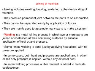
Learn about gas welding using oxyacetylene torch, fusion welding, and pressure welding techniques for solid materials. Discover welding principles, types of joints, and the importance of surface preparation.

E N D
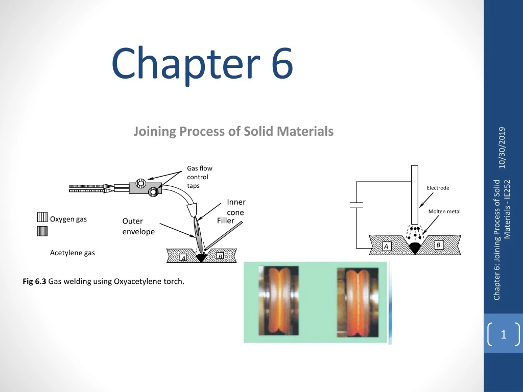
Electrode Gas flow control taps Molten metal B A Inner cone Filler Outer envelope Oxygen gas Acetylene gas B A Fig 6.3 Gas welding using Oxyacetylene torch. Chapter 6Joining Process of Solid Materials Chapter 6: Joining Process of Solid Materials - IE252
Chapter 6Joining Process of Solid Materials Chapter 6: Joining Process of Solid Materials - IE252
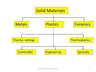
6.1 Joining technology In general, joining components is usually classified as: Permanent or non-permanentjoining process • Permanent localized coalescence based on cohesionand/or adhesionbetween joining elements (Type 1), or • Geometrical elastic or plastic locking of the joining elements (Type 2), or • Using special joining elements like wedges, nails, bolts, ..etc. (Type 3).(based on generating stresses (elastic or plastic type) between the joined elements) PERMANENT NON-PERMANENT Chapter 6: Joining Process of Solid Materials - IE252
6.1 Joining technology In general, joining components is usually classified as: Permanent or non-permanentjoining process Chapter 6: Joining Process of Solid Materials - IE252
6.2 Joining technique based on cohesion and/or adhesion principles In cohesion: the elements are generally of the same metallic crystals and the coalescence is established by the supply of temperature or pressure or combination to create the required coalescence. Hence, the coalescence is based on atomic bonding forces between the two components. Friction and resistance spot welding process required: Supply heat + pressure In Adhesion : the coalescence between the two joining elements is established by bonding using surface physical forces. It is not necessary to have common metallic structure for the joining elements. Fusion welding process required: Supply heat only Chapter 6: Joining Process of Solid Materials - IE252 Adhesive bonding , soldering,
6.2 Joining technique based on cohesion and/or adhesion principles • To achieve a satisfactory joining process based on coalescence of cohesion or adhesion, two basicrequirements must be fulfilled: • The surfaces involved must be free of oxide layer, absorbed gases, and other contaminations. • The surfaces involved must be brought into intimate contact so that the bonding force activated. Chapter 6: Joining Process of Solid Materials - IE252
6.2 Joining technique based on cohesion and/or adhesion principles Different techniques are generally employed to achieve these requirements. Table 6.1, provides how these conditions fulfilled for different joining processes Chapter 6: Joining Process of Solid Materials - IE252 Type 1 is characterized as a high temperature welding process (fusion welding processes), While type 2 is characterized as a pressure (pressure welding processes)
High Temperature (below melting point) at medium Pressure.(e.g. spot welding) High Pressure, P (Pressure welding process High Temperature , T (Fusion welding process Fig 6.2 Schematic illustration of useful combination of high pressure and high temperature (below melting point) e.g. resistance spot welding process. 6.2 Joining technique based on cohesion and/or adhesion principles Type 1 is characterized as a high temperature welding process (fusion welding processes), While type 2 is characterized as a pressure (pressure welding processes) Chapter 6: Joining Process of Solid Materials - IE252 In between, these parameters (high pressure and temperature): It is possible to fulfill these conditions in the development of new and different welding processes. For example, resistant spot welding achieved by heating the two strips to forging temperature (below melting point) then applying pressure. Hence, the basic process of resistant spot welding are thermal (heating) and mechanical (plastic deformation).
In fusion welding, the coalescence between the two joining elements is established by localized melting of the joining surfaces to create cohesion based. • Melting metal in the joining pool must be prevented or shielded from oxidation or possible contamination that result in porous weld will decrease welding strength. • Two type of energy are common in fusion welding, electric and chemical energies. 6.3 Fusion Welding Chapter 6: Joining Process of Solid Materials - IE252
6.3 Fusion Welding • 6.3.1 Fusion welding based on electric energy (arc welding) • Fusion welding based on electric energy by arcing is achieved through the following steps : • Creating the arc, • Supplying the filling material, and • Protection or shielding the molten metal in welding pool. Creating the arc by establishing the different voltage between electrode and workpeice which is controlled using the following equation: Where, K: constant less than 1 related to heat losses. I : Current. R: Resistance of ionized air gap. t : Welding time. Chapter 6: Joining Process of Solid Materials - IE252 Supply filling material using either consumable electrode (as filling material, melting point < arc temperature), or using non-consumable electrode (separate feeding the filler wire) where the melting point of electrode is > arc temperature.
6.3 Fusion Welding • 6.3.1 Fusion welding based on electric energy (arc welding) • Fusion welding based on electric energy by arcing is achieved through the following steps : • Creating the arc, • Supplying the filling material, and • Protection or shielding the molten metal in welding pool. • Protection or shielding the molten metal pool against oxidation, contamination, stabilizing arcing, and decreasing cooling rate through different techniques: • Coating the consumable electrode by fluxing material • Covering the arc with granulated fluxing material, or • Supply inert gas in melting pool. Chapter 6: Joining Process of Solid Materials - IE252
Electrode Molten metal B A 6.3 Fusion Welding • 6.3.2 Arc welding processes • Metal-electrode arc welding process: • The arc in this welding process, is maintained between a bar (consumable electrode) and work material. • The arc is not stable, and created for short period of time. • The process applied for special applications, like stud welding. During stud welding and after arcing, the stud pressed in work piece. Chapter 6: Joining Process of Solid Materials - IE252
Electrode Molten metal B A 6.3 Fusion Welding • 6.3.2 Arc welding processes • Metal-electrode arc welding process: • The arc in this welding process, is maintained between a bar (consumable electrode) and work material. • The arc is not stable, and created for short period of time. • The process applied for special applications, like stud welding. During stud welding and after arcing, the stud pressed in work piece. Chapter 6: Joining Process of Solid Materials - IE252
B A Electrode Extruded coating flux Gas shielding Molten metal 6.3 Fusion Welding • 6.3.2 Arc welding processes • 2) Shielded metal-arc welding process: • In shielded metal-arc welding process, the electrode consists of wire or rod (2-10mm diameter) extruded with special fluxing powder on outer surface, creating gas shielding on melting. • Here, the arc is stable and continuous. 90% of manual arc welding is shielded arc welding process. Chapter 6: Joining Process of Solid Materials - IE252
B A Electrode Granulated Powder Molten metal 6.3 Fusion Welding • 6.3.2 Arc welding processes • 3) Submerged arc welding process: • In submerged arc welding, the metal arc is shielded using granulated powder. • The process is similar to shielded-metal-arc welding. The electrode is feed using coiled copper coated electrode wire. T • he process is very common in shipbuilding, large tank welding and tube and oil pipeline welding Chapter 6: Joining Process of Solid Materials - IE252
B A Consumable Electrode (filler) Inert gas Molten metal 6.3 Fusion Welding • 6.3.2 Arc welding processes • 5) Gas metal arc welding (MIG): • In MIG welding, a filler electrode (commonly coiled wire type) is fed to melting pool and shielded using inert gases. • It is used to produce high quality welding, both automated and manual processes are common. • Co2 gas is common for shielded steel weld, while Helium is common for shielding non-ferrous welds Chapter 6: Joining Process of Solid Materials - IE252
Non-consumable Electrode Inert gas Filler wire B A 6.3 Fusion Welding • 6.3.2 Arc welding processes • 5) Gas tungsten-arc weld (TIG): • In TIG welding, is similar to MIG welding process, however, electrode is non-consumable type (Tungsten material)and filler metal supplied externally. • Same shielding method like MIG weld is also used. • The process commonly called Tungsten-inert-gas process (TIG) Chapter 6: Joining Process of Solid Materials - IE252 Stainless-steel TIG welding without filler
Gas flow control taps Inner envelope flame Filler Outer envelope Oxygen gas Acetylene gas B A 6.3 Fusion Welding • 6.3.3 Fusion welding based on chemical energy (gas welding) • The thermal energy necessary for fusion welding is established through chemical energy by the combustion of Oxygen and Acetylene in special Oxyacetylene torch. Chapter 6: Joining Process of Solid Materials - IE252 • By adjusting the gas flow taps of both Oxygen and Acetylene it is possible to have three types of flames: • Neutral flame which is common for most welding process. • Oxidizing flame which is common for welding brass and bronze metals (access Oxygen). • Carbonized or reduced flame commonly used for special weld, like tool steel (access Acetylene).
Gas flow control taps Inner envelope flame Filler Outer envelope Oxygen gas Acetylene gas B A 6.3 Fusion Welding • 6.3.3 Fusion welding based on chemical energy • (gas welding) • By adjusting the gas flow taps of both Oxygen and Acetylene it is possible to have three types of flames: Chapter 6: Joining Process of Solid Materials - IE252 • Neutral flame which is common for most welding process. • Oxidizing flame which is common for welding brass and bronze metals (access Oxygen). • Carbonized or reduced flame commonly used for special weld, like tool steel (access Acetylene).
Simple butt joint Simple butt joint (Thick plate) Single “V” joint Single “V” joint (thick plate 4-30mm) Double “V” joint Double “V” joint (thick plate 20-25mm) (b) Single “U” joint (a) Single “J” joint (thick plate >25mm) Fig 6.4 (a) Welding joints, (b) Welding applications. 6.3 Fusion Welding Chapter 6: Joining Process of Solid Materials - IE252
6.3 Fusion Welding Butt joint notations Welding notations Corner joint notations Chapter 6: Joining Process of Solid Materials - IE252 Lap Joint notation T-joint notation
6.4 Pressure Welding 6.4.1 Cold welding • The coalescence in cold weld is based mainly on high pressure with no heating and is achieved using mechanical basic process using plastic deformation. • The application of cold weld covers small parts like electric wire terminals (e.g. electronic computer wire connection) and seaming sheet metals A grooving tool produces the final shape Both pieces of sheet metal are folded The pieces are interlocked Chapter 6: Joining Process of Solid Materials - IE252
6.4 Pressure Welding 6.4.1 Cold welding • 6.4.2 Resistance pressure welding • In resistance welding process, the pressure is decreased and the work-piece is heated to forging temperature (below melting point). • Electric current is passed between electrodes and work-piece required to increase the work-piece temperature, next the pressure is applied via water-cooled electrodes to provide the required coalescence. Chapter 6: Joining Process of Solid Materials - IE252
6.4 Pressure Welding 6.4.1 Cold welding • 6.4.2 Resistance pressure welding • In resistance welding process, the pressure is decreased and the work-piece is heated to forging temperature (below melting point). • Electric current is passed between electrodes and work-piece required to increase the work-piece temperature, next the pressure is applied via water-cooled electrodes to provide the required coalescence. Chapter 6: Joining Process of Solid Materials - IE252
Electrodes Strip A Strip B Nugget 6.4 Pressure Welding 6.4.1 Cold welding • 6.4.2 Resistance pressure welding • 6.4.3 Resistance welding processes • Resistance spot welding process: Commonly two cylindrical electrodes with conical ends are used, while the two strip of metals in-between. Both similar and dissimilar electrode diameters are used with spot welding process. Dissimilar electrode diameters are used when welding sheet metal having dissimilar sheet metal thickness or materials. Operation range for steel strips: current: 200-100 Amp, time: 0.15-1.0 sec, and pressure: 70-100 N/mm2 for steel strips. Sheet metal thickness between 3-4 mm. Chapter 6: Joining Process of Solid Materials - IE252
Rotating disk electrodes. Seam Strip A Strip B 6.4 Pressure Welding 6.4.1 Cold welding • 6.4.2 Resistance pressure welding • 6.4.3 Resistance welding processes • 2. Resistance seam welding process: • Commonly two round disks are used as electrodes and power driven, while two strip of metals in-between. • This will result in a series of continuous spots along welding direction. • The two disks are pressed toward the two sheet metal strips during disk rotation. Similarly, the two disk electrodes are water cooled. • This type of weld will provide sealing compare to spot weld process, hence, it is used for applications like liquid tanks, oil tanks, water tanks ..etc. The material cover ferrous and non-ferrous metals like stainless steel tanks used for food industries. Chapter 6: Joining Process of Solid Materials - IE252
Pressure Two flat electrodes Strip A Strip B 6.4 Pressure Welding 6.4.1 Cold welding • 6.4.2 Resistance pressure welding • 6.4.3 Resistance welding processes • 3. Resistance projection welding process: • Commonly two round disks are used as electrodes and power driven, while two strip of metals in-between. • This will result in a series of continuous spots along welding direction. • The two disks are pressed toward the two sheet metal strips during disk rotation. Similarly, the two disk electrodes are water cooled. • This type of weld will provide sealing compare to spot weld process, hence, it is used for applications like liquid tanks, oil tanks, water tanks ..etc. The material cover ferrous and non-ferrous metals like stainless steel tanks used for food industries. Chapter 6: Joining Process of Solid Materials - IE252
6.4 Pressure Welding • 6.4.4 Other pressure and resistance welds Two types of butt welding are common, upset butt welding and flash butt welding. Both techniques are common for welding two similar of similar or dissimilar rods or pipes. In upset butt welding: The mating surfaces are brought into each other using low pressure, next the current is allowed to flow resulting in heating the mating surfaces. Gradually, the pressure is increased to form upset weld. Pressure Pressure Rod A Rod B (a) Upset butt rod welding Chapter 6: Joining Process of Solid Materials - IE252
Flash Pressure Pressure Rod A Rod B (b) Flash butt rod welding 6.4 Pressure Welding • 6.4.4 Other pressure and resistance welds Two types of butt welding are common, upset butt welding and flash butt welding. Both techniques are common for welding two similar of similar or dissimilar rods or pipes. In flash butt welding: The mating surfaces are brought at controlled speed. When the highest points or asperities approach each other, a large current flow result in melting and boiled away. When the next highest points approaching each other, the process is repeated, and so on. Flash butt weld required very complicated controller to carry out the welding process compare to upset butt weld. Hence, it is more expensive when compared to upset butt welding process. However, high quality welding achieved using the flash weld. Chapter 6: Joining Process of Solid Materials - IE252
Two chucks Rotation Pressure Pressure Rod B Rod A Friction rod welding 6.4 Pressure Welding • 6.4.5 Friction weld • In friction welding, the heat is provided using mechanical friction established by relative motion between the welded elements plus pressure. Welding process carried-out using the following steps: • The first rod is kept stationery, while the second is rotating and pressed toward the second rod. • When temperature rising up (fusion temperature), rotation stopped and pressure maintained or even increased until weld is completed. Chapter 6: Joining Process of Solid Materials - IE252
Two chucks Rotation Pressure Pressure Rod B Rod A Friction rod welding 6.4 Pressure Welding • 6.4.5 Friction weld Chapter 6: Joining Process of Solid Materials - IE252
6.4 Pressure Welding • 6.4.5 Friction weld – Applications Chapter 6: Joining Process of Solid Materials - IE252
6.4 Pressure Welding • 6.4.5 Pressure gas welding process • Pressure gas weld is common for welding butt weld is of two bars or pipes. • In pressure gas weld. • Oxyacetylene torch is used as source of heat. When temperature reaches the fusion temperature, the rods pressed against each other to develop the required weld. Chapter 6: Joining Process of Solid Materials - IE252
6.5 Joining processes based on filler materials of Tf <Tw(Brazing, soldering, and adhesive bonding) • The coalescence of the joining elements are based on adhesion or surface forces generated between the contact surfaces using filler material with melting point less than work piece melting point (Tf <Tw) . • This type of joining processes is divided into two groups: (a) brazing and soldering, and (b) adhesive boning technology. Chapter 6: Joining Process of Solid Materials - IE252
6.5 Joining processes based on filler materials of Tf <Tw(Brazing, soldering, and adhesive bonding) 6.5.1 Brazing, soldering and braze welding • Brazing and soldering are permanent joining processes for similar and dissimilar materials. This is achieved by supplying non-ferrous metals as filler material. For example, brazing of mild-steel-galvanized steel, stainless steel to copper, mild steel to stainless-steel, mild-steel to cast iron. • The filler material is distributed based on capillary actionin case of brazing and soldering processes, while distributed by gravity in case of braze welding process. • Brazing is ideal for manufacture of bicycle frames, refrigeration and air conditioning cooling circuit tubing system. • Braze / bronze welding provides a strong joint and is ideal of steel frames, where a certain amount of flexibility is required. The filler rod is broader than that used in brazing. Chapter 6: Joining Process of Solid Materials - IE252
6.5 Joining processes based on filler materials of Tf <Tw(Brazing, soldering, and adhesive bonding) 6.5.1 Brazing, soldering and braze welding • Brazing and soldering are permanent joining processes for similar and dissimilar materials. This is achieved by supplying non-ferrous metals as filler material. For example, brazing of mild-steel-galvanized steel, stainless steel to copper, mild steel to stainless-steel, mild-steel to cast iron. • The filler material is distributed based on capillary actionin case of brazing and soldering processes, while distributed by gravity in case of braze welding process. • Brazing is ideal for manufacture of bicycle frames, refrigeration and air conditioning cooling circuit tubing system. • Braze / bronze welding provides a strong joint and is ideal of steel frames, where a certain amount of flexibility is required. The filler rod is broader than that used in brazing. Chapter 6: Joining Process of Solid Materials - IE252
6.5 Joining processes based on filler materials of Tf <Tw(Brazing, soldering, and adhesive bonding) 6.5.1 Brazing, soldering and braze welding • In soldering, the melting point of filler material is less than 450 deg. While its grater than 450 deg for brazing and braze welding processes. • Some applications for brazing, soldering and braze welding Brazing copper pipes Brazing carbide tip on tool holder Chapter 6: Joining Process of Solid Materials - IE252 Soldering copper pipes Braze weld copper pipes
6.5 Joining processes based on filler materials of Tf <Tw(Brazing, soldering, and adhesive bonding) 6.5.1 Brazing, soldering and braze welding • In soldering, the melting point of filler material is less than 450 deg. While its grater than 450 deg for brazing and braze welding processes. • Special work piece setup is required for allowing the capillary action. For example, small gaps or clearances must be created between the mating surfaces and supplying fluxing material are important for efficient operation of capillary action Brazing copper pipes Chapter 6: Joining Process of Solid Materials - IE252 soldering copper pipes
6.5 Joining processes based on filler materials of Tf <Tw(Brazing, soldering, and adhesive bonding) 6.5.1 Brazing, soldering and braze welding • There are two common solder alloys : • Alloy of tin (40%), lead (60%) and antimony (<0.5%), having melting temperature of 250 deg. • Alloy of tin, zinc and cadmium which is common for soldering light metals with working temperature of up to 300 deg. • Shearing strength between 25-50 N/mm2 with work piece clearance between 0.25mm to 0.025mm. • Heating source and applications: • Chemical (torch flame) for joining refrigeration and air conditioning pipes as well as water pipes (soldering or brazing). • Electric (resistance) or induction for electric conductor joining processes (soldering or brazing). • Thermal (soldering iron) or furnaces (induction), metal bath and salt bath. Chapter 6: Joining Process of Solid Materials - IE252
6.5 Joining processes based on filler materials of Tf <Tw(Brazing, soldering, and adhesive bonding) 6.5.1 Brazing, soldering and braze welding Table 6.4 shows a list of common fillers for brazing metals and their applications. Chapter 6: Joining Process of Solid Materials - IE252
Pipe A Pipe B Adhesive or brazing material Strip A Strip B Adhesive or brazing material Bonded overlap joint Bonded pipe joint Fig 6.6 Bonded/brazing technologies. 6.5 Joining processes based on filler materials of Tf <Tw(Brazing, soldering, and adhesive bonding) 6.5.1 Brazing, soldering and braze welding. 6.5.2 Adhesive bonding • In adhesive bonding, both metallic and nonmetallic, similar and dissimilar materials can be joined through the adhesive material distributed between the interfaces of the elements using adhesion (surface forces). • The surface force is established between elements and adhesive material. Chapter 6: Joining Process of Solid Materials - IE252 • The primary basic process in adhesive bonding technology, is mechanical (placing adhesive material in joint), and chemical secondary basic process (adhesive hardening).
6.5 Joining processes based on filler materials of Tf <Tw(Brazing, soldering, and adhesive bonding) 6.5.1 Brazing, soldering and braze welding. 6.5.2 Adhesive bonding • Nearly all types of materials can be joined by adhesive bonding technology. Joining metals using bonding technology increased rapidly in the last 10 year ago. • Sometimes, the structure bolted or spot-welded and also boned at the same time. This technique called joining metal using weld-bonded or bolt-bonded technology. Chapter 6: Joining Process of Solid Materials - IE252
6.5 Joining processes based on filler materials of Tf <Tw(Brazing, soldering, and adhesive bonding) 6.5.1 Brazing, soldering and braze welding. 6.5.2 Adhesive bonding • Nearly all types of materials can be joined by adhesive bonding technology. Joining metals using bonding technology increased rapidly in the last 10 year ago. • Sometimes, the structure bolted or spot-welded and also boned at the same time. This technique called joining metal using weld-bonded or bolt-bonded technology. Chapter 6: Joining Process of Solid Materials - IE252 • Adhesive bonding structure provides more damping compared to traditional mechanical joining structures. It also increases corrosion resistance properties and also enhance the mechanical properties of the structure. • However, to obtain good results from bonded structure, it is very important to clean the bonded elements from any oil or contamination. Failing to do so, will result in weak bonded structure.
6.5 Joining processes based on filler materials of Tf <Tw(Brazing, soldering, and adhesive bonding) 6.5.1 Brazing, soldering and braze welding. 6.5.2 Adhesive bonding • Two types of adhesive materials are exist, thermo-setting and thermoplastic type. Adding some chemicals to adhesive material, will improve the viscosity and/or the mechanical strength or chemical resistance properties. • Adhesive material is commonly distributed with hardening agent. The hardening agent mixed with adhesive material with specific percentage specified by the manufacturer, e.g. 80% weight adhesive material and 20% weight hardener material). • More information about adhesive materials can be founded in literatures. Chapter 6: Joining Process of Solid Materials - IE252
Problems from pervious examinations Question 1 Complete the following statements • In cohesion based welding: the elements are generally of the same metallic crystals and the coalescence is established by the supply of temperature or pressure or combination to create the required coalescence. Hence, the coalescence is based on ………….. between the two components. • In Adhesion based welding : the coalescence between the two joining elements is established by ………forces. It is not necessary to have common metallic structure for the joining elements. • To achieve a satisfactory joining process based on coalescence of cohesion or adhesion, two basicrequirements must be fulfilled, 1) The surfaces involved must be ………………………… 2) The surfaces involved must be ……………………………………………. • Welding process based on high temperature non pressure like ……………..welding process, or high pressure with no heating like …………..welding process, or a combination of temperature and pressure like …………welding process. • Protection or shielding the molten metal pool against oxidation, contamination, stabilizing arcing, and decreasing cooling rate through different techniques, 1)………………………………… 2) …………………………………………………………….3)………………………………. . • Brazing and soldering are permanent joining processes for similar and dissimilar materials. This is achieved by supplying non-ferrous metals as filler material. The filler material is distributed based on ………… action in case of brazing and soldering processes, while distributed by ……. in case of braze welding process. Chapter 6: Joining Process of Solid Materials - IE252
B A Electrode Extruded coating flux Gas shielding Molten metal Problems from pervious examinations Question 2 • How filling material distributed in Brazing, Soldering and Braze welding processes? • It is required to weld two types of pipes, the first pipe made of steel and the second made of plastic. Suggest the suitable welding process for this application? • What is the main difference between MIG and TIG welding process, sketch the two process? • Question 3: • Name the following welding process: ………….. Chapter 6: Joining Process of Solid Materials - IE252
Problems from pervious examinations Question 4 • State type of welding process for the following product/application: Chapter 6: Joining Process of Solid Materials - IE252