Download
1 / 22
220 likes | 411 Vues
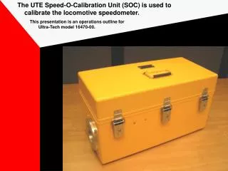
The UTE Speed-O-Calibration Unit (SOC) is used to calibrate the locomotive speedometer. This presentation is an operations outline for Ultra-Tech model 16470-00. Caution:.

E N D
The UTE Speed-O-Calibration Unit (SOC) is used to calibrate the locomotive speedometer. This presentation is an operations outline for Ultra-Tech model 16470-00.
Caution: The Operator of this equipment must know and follow general safety procedures concerning electrical and mechanical equipment or be supervised by a qualified trainer.
Setup: Measure and make note of locomotive wheel diameter. The locomotive’s axle alternator is then removed and connected to the Speedometer Calibration Unit (SCU).
Open Control Box and confirm that switch is OFF and control is fully counter clockwise.
Attach cable connectors: The connector with the yellow power cable connects to the control box.
The main case uses the connector without the yellow power cable.
Power is normally supplied by connecting the SCU clips to the locomotive DC supply; a workbench supply can also be used (as shown). Observe proper polarity. If polarity is reversed, unit will appear to be dead (no power).
Power Up: Confirm the setup procedure before power up. - Locomotive axle alternator connected to the SCU. - Cable connectors correctly attached. - Power supply properly connected (approx. 72V DC). - Speed control set to minimum (counter clockwise).
Turn power switch ON and allow the SCU control software to get to the main menu.
Follow the displayed instructions. Select for “WhDia” wheel diameter.
INCR (increase) or DECR (decrease) the displayed wheel diameter.
Select ENTER when displayed wheel diameter equals measured diameter.
The top line display should now show the selected wheel diameter and the default target speed.
Operation: Auto Mode – If auto mode is selected, the speed control must stay at the home position (completely counter clock-wise).The target speed can be changed by pushing the INCR or DECR buttons.The SCU will automatically adjust the axle alternator to the targeted test speed. Manual Mode – If manual mode is selected, the speed control is manually adjusted until the top line speed is nearly equal to the bottom line speed (target speed). Speedometer calibration is usually done in AUTO mode.
In either mode: • The axle alternator speed is adjusted to match the target speed (manually or automatically). • The target speed can be changed by pushing the INCR or DECR buttons. • Speed is measured in MPH. • The axle alternator speed will flash when it is more than 1 mph different than the target speed. Note: The axle alternator speed must be adjustable to be within FRA tolerances! +/- 3 MPH for 20 & 22 MPH +/- 5 MPH for 40, 60, 72 & 75 MPH.
Auto Mode Operation: After following the setup and power up procedures, select auto mode. The back button can be used to get back to previous menus.
Confirm speed control is at minimum (counter clock-wise). Push “Done” button to continue.
Increase or decrease target speed. Target speed is on the bottom line of the display. Encoder speed adjustments are to be within tolerance at each target speed.
Power Down: Minimize speed control and turn OFF power switch.
Conclusion: This is the end of this presentation. If you want more information, please see the Instruction and Operations manual 16470-99.