Memory Cells: Ferrite Core vs. Semiconductor Memory
Explore the principles of ferrite core and semiconductor memory cells, comparing their structure, operation, and characteristics. Learn about dynamic RAM, static RAM, and their differences in terms of speed, cost, and construction.

Memory Cells: Ferrite Core vs. Semiconductor Memory
E N D
Presentation Transcript
Memory Cell • Basic element – memory cell • Exhibit 2 stable states used to represent 0 and 1 • Can be written into (at least once) • Can be read to sense state
Ferrite Core Memory • Before semiconductor memory: core memory • Magnetic core, 1 core = 1 bit • Destructive read • Obsolete Exerted from Wikipedia
Ferrite Core Memory • Principle • The major property that makes core memory work is the hysteresis of the magnetic material used to make the toroid. • Only a magnetic field over a certain intensity (generated by the wires through the core) will cause the core to change its magnetic polarity (or state from '0' to '1'). • To select a memory location, one of the X and one of the Y lines are driven with half the current required to cause this change. • Only the combined magnetic field generated at the intersection the driven X and Y lines is sufficient to change the state of the bit. Exerted from Wikipedia
Ferrite Core Stack 16Kword PDP-11Core Module
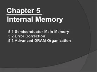
Semiconductor Memory • RAM • Misnamed as all semiconductor memory is random access • Read/Write • Volatile • Temporary storage • Static or dynamic
Dynamic RAM • Bits stored as charge in capacitors • Charges leak • Need refreshing even when powered • Need refresh circuits • Simpler construction • Smaller per bit • Less expensive • Slower • Main memory • Essentially analogue • Level of charge determines value
Dynamic RAM Structure ‘High’ Voltage at Y allows current to flow from X to Z or Z to X Y nMOS (n-channel MOSFET) one transistor and one capacitor per bit X Z
Dynamic RAM Structure • nMOS Transistor • Since the silicon channel b/w the source & drain is of p-type silicon, if a positive voltage is applied to the gate electrode, it will make the n-channel b/w drain and source
Dynamic RAM Structure • Charging & discharging characteristics of the storage capacitor
DRAM Operation • Address line active when bit read or written • Transistor switch closed (current flows) • Write • Voltage to bit line • High for 1 low for 0 • Then signal address line • Transfers charge to capacitor • Read • Address line selected • transistor turns on • Charge from capacitor fed via bit line to sense amplifier • Compares with reference value to determine 0 or 1 • Capacitor charge must be restored
SRAM (Array 구조) • 2n words of 2m bits each • 그림에서 column은 총 4개, 즉, 22 bits • Row는 총 24개(16개),즉 16 words • 여기서 한 word는 4 bits
Static RAM • SRAM cell is a bi-stable flip-flop • Bits stored as on/off switches • No charges to leak • No refreshing needed when powered • Does not need refresh circuits • More complex construction • Larger per bit • More expensive • Faster • Cache • Digital • Uses flip-flops
1 0 0 1 Static RAM Structure six transistors per bit (“flip flop”) (일반적으로 word line이라고 함)
Static RAM Operation • Transistor arrangement gives stable logic state • State 1 • C1 high, C2 low • T1 T4 off, T2 T3 on • State 0 • C2 high, C1 low • T2 T3 off, T1 T4 on • Address line transistors T5 T6 is switch • Write • (1) apply value to B & (2) Raise word line (address line) • Read • (1) value is on line B (2)raise word line
SRAM Read • Precharge both bitlines(bit, bit_b) high • Then turn on word line • One of the two bit lines will be pulled down by the cell • 예: A=0, A_b=1 값을 가지고 있다고 가정 • bit discharges, bit_b stays high • But A bumps up slightly • Read stability • N1 >> N2 이어야(drive 능력 갖춰야 함) • A=0이므로 bit값을 읽으면 최종 0이됨 • 아래 그림을 보면,bit, bit_b가모두 1로 되어 있다가 word가 활성화되니(읽고자 하니) A(0)값에 의해 bit이 0이 됨을 알 수 있음
1 0 SRAM Write • Drive one bitline high, the other low • Then turn on word line • Bitlines overpower cell with new value • 예: A=0, A_b=1, bit=1, bit_b=0 가정 • Turn on word line • From bit(1), bit_b(0), force A to high, A_b to low • Writability • Must overpower feedback inverter • N2 >> P1 1 0 • 위와 같은 값의 인가로 A의 값이 01로 바뀜(write) • A_b는 10으로 바뀜(write)
SRAM 크기 • High bitlines must not overpower inverters during reads • But low bitlines must write new value into cell P1 P2 N2 N4 N1 N3 • Read stability • N1 >> N2 이어야(drive 능력 갖춰야 함) • Writability • Must overpower feedback inverter • N2 >> P1
SRAM Column Example(Read 모델) • word_q1 값을 high로해서 SRAM 값을 읽고자 함 • Bit_v1f(out_b_v1r)와 bit_b_v1f(out_v1r)값을 얻음
SRAM Column Example( Write 모델) 1. Charging 회로에 의해 bit line에 값이 인가됨 2. Wordline을 turn on 함 4. 그림에서 bit_v1f 값은 01로, 새로운 값이 쓰여짐 3. Bit line 값에 의해 cell의 값이 overpower 됨
SRAM (Decoder) • n:2n decoder consists of 2n n-input AND gates • One needed for each row of memory • Build AND from NAND or NOR gates If A1A0 =00 If A1A0 =01 If A1A0 =10 If A1A0 =11
SRAM (Column Circuitry) • SRAM의 Column에는 다음과 같은 회로가 필요함 • Bitline Conditioning • Precharge bitlines high before reads • 읽기전에 bit line을 precharing함 • Sense Amplifier • Latch형 혹은 Differential sense amplifier가 존재하며, 신호를 증폭하는 역할을 함 • 예를 들어, 메모리 셀로부터 읽은 데이터를 증폭하는 역할수행
Static RAM Structure • Cell size is critical: 26 x 45 λ (even smaller in industry) • Tile cells sharing VDD, GND, bitline contacts
SRAM v DRAM • Both volatile • Power needed to preserve data • Dynamic cell • Simpler to build, smaller • More dense • Less expensive • Needs refresh • Larger memory units • Static • Faster • Cache
Read Only Memory (ROM) • Permanent storage • Nonvolatile • Microprogramming (see later) • Library subroutines • Systems programs (BIOS) • Function tables
Types of ROM (1) • Mask ROM • Written during manufacture • Very expensive for small runs • Programmable (once) • PROM • Read-only, write-once • Needs special equipment to program • Erasable Programmable (EPROM) • R/W • Have to erase before write • Erased by UV
Types of ROM (2) • Electrically Erasable (EEPROM) • R/W • Takes much longer to write than read • Individual bytes programmable • Flash memory • Can be erased electrically • In circuit programmability • Need to be erased and reprogrammed • Erase whole chip • Erase block by block • Programming is different from EPROM • Reading is same as EPROM/PROM
NOR vs. NAND FLASH • NOR – Intel in 1988 • NAND – Toshiba in 1989
Organisation in detail • A 16Mbit chip can be organised as 1M of 16 bit words • A bit per chip system has 16 lots of 1Mbit chip with bit 1 of each word in chip 1 and so on • A 16Mbit chip can be organised as a 2048 x 2048 x 4bit array • Reduces number of address pins • Multiplex row address and column address • 11 pins to address (211=2048) • Adding one more pin doubles range of values so x4 capacity
Typical 16 Mb DRAM (4M x 4) RAS = Row Addr. Select CAS = Column Addr. Select WE = Write Enable OE = Output Enable a typical organization of a 16-Mbit DRAM. 4 bits are read or written at a time. Logically, the memory array is organized as four square arrays of 2048 by 2048 elements. 2 k x 2 k = 4 M를 4개 사용
Module Organization 256K byte 256K = 218 = 29 29 1 byte = 8 bits If a RAM chip contains only 1 bit per word, then clearly we will need at least a number of chips equal to the number of bits per word. This figure shows how a memory module consisting of 256K 8-bit words could be organized. For 256K words, an 18-bit address is needed and is supplied to the module from some external source (e.g., the address lines of a bus to which the module is attached). The address is presented to 8 256K * 1-bit chips, each of which provides the input/output of 1 bit.
1MByte Module Organization A B C D Groups 256 k 256 k 256 k 256 k 4개 256K중에서 하나 선택
Error Correction • Hard Failure • Permanent defect • Soft Error • Random, non-destructive • No permanent damage to memory • Detected using Hamming error correcting code • Logic included to detect/correct errors using Hamming error correcting code • For an M-bit data, M-bit data + K-bit code = (M+K)-bit codeword is stored
Error Correcting Code Function Error detected but cannot be corrected No error Error detected and can be corrected
A B A B 1 1 1 0 1 1 1 0 1 0 0 C C Hamming Code Fill the remaining compartments with parity bits. Make the total number of bit -1 in a circle must be even. For example: The data bits in A = 1+1+1 = 3. This is odd – therefore add an additional bit -1 to circle A Assign data bits to the inner compartments.
A B 1 1 1 0 C Hamming Code A B A B 1 1 1 0 1 0 1 1 0 1 0 0 0 0 0 C C If a bit gets erroneously changed, the parity bits in that circle will no longer add up to 1. Errors are found in A and C – and the shared bit in A and C is in error and can be fixed.
Error Correcting and Detecting (1) code word K는 M+K 길이의 코드 위치를 모두 표현해야 하므로 2K-1 값을 가져야 함 • Given an M-bit data is to be stored • Step 1. Calculate the value for K, the # of code bits 2K – 1 M + K • Step 2. Position M data bits and K code bits in codeword. code bits position number are power of 2 • Step 3. Use evenparity to calculate the code bits’ values • How to correct error when a codeword is retrieved • Step 1. Recalculate code bits’ value • Step 2. Syndrome = old code bits XOR new code bits • Step 3. If Syndrome = 0 then no error else Syndrome = error position flip that bits
Error Checking Overhead M K 2K-1 M + K
C1 = D1 D2 D4 D5 D7 C2 = D1 D3 D4 D6 D7 C3 = D2 D3 D4 D8 C4 = D5 D6 D7 D8 Single Bit Errors in 8-bit words • Data and check bits arranged into a 12-bit word. • Bit positions numbered from 1 to 12. • Bit positions representing position numbers that are powers of 2 are designated as check bits. • Check bits calculated as follows: • Data and check bits arranged into a 12 bit syndrome word: 4 check bits 8 data bits
Calculating check bits C1 = D1 D2 D4 D5 D7 Each check bit works on every data bit who shares the same bit position
Example D8 D1 • Input word: 00111001 Databit D1 in rightmost position • Calculate check bits: C1 = 1 0 1 1 0 = 1 C2 = 1 0 1 1 0 = 1 C3 = 0 0 1 0 = 1 C4 = 1 1 0 0 = 0Stored word = 001101001111 • If data bit 3 sustains an error (001101101111) C1 = 1 0 1 1 0 = 1 C2 = 1 1 1 1 0 = 0 C3 = 0 1 1 0 = 0 C4 = 1 1 0 0 = 0 • Calculate syndrome word:0110 = bit position 6. • D3 resides in bit position 6.
Error Correcting and Detecting (2) • Hamming code only correct single error: SEC • Can we also detect 2 errors in addition? SEC-DED • Include one more bit: p bit • Given an M-bit data is to be stored, add Step 4 • Step 4. Use even parity on all codeword bits to calculate p bit’s values • How to correct/detect error when a codeword is retrieved, modify Step 3 • Step 3. If Syndrome = 0 then no error else Syndrome = error position flip that bit Recalculate p bit’s value If old p new p then 2 errors cannot be corrected
Hamming SEC-DEDCode * * The 8th bit that makes total number of 1’s even can detect the occurrence of double bits error Wrong correction Wrong detection
Advanced DRAM Organization • Basic DRAM same since first RAM chips • Enhanced DRAM • Contains small SRAM as well • SRAM holds last line read (c.f. Cache!) • Cache DRAM • Larger SRAM component • Use as cache or serial buffer
Synchronous DRAM (SDRAM) • Access is synchronized with an external clock • Address is presented to RAM • RAM finds data (CPU waits in conventional DRAM) • Since SDRAM moves data in time with system clock, CPU knows when data will be ready • CPU does not have to wait, it can do something else • Burst mode allows SDRAM to set up stream of data and fire it out in block • DDR-SDRAM sends data twice per clock cycle (leading & trailing edge)
RAMBUS • Adopted by Intel for Pentium & Itanium • Main competitor to SDRAM • Vertical package – all pins on one side • Data exchange over 28 wires < cm long • Bus addresses up to 320 RDRAM chips at 1.6Gbps • Asynchronous block protocol • 480ns access time • Then 1.6 Gbps