Chapter 4 Circuit-Switching Networks
Chapter 4 Circuit-Switching Networks. Multiplexing SONET Transport Networks Circuit Switches The Telephone Network Signaling Traffic and Overload Control in Telephone Networks Cellular Telephone Networks. Circuit Switching Networks. End-to-end dedicated circuits between clients


Chapter 4 Circuit-Switching Networks
E N D
Presentation Transcript
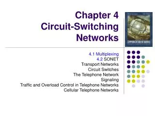
Chapter 4 Circuit-Switching Networks Multiplexing SONET Transport Networks Circuit Switches The Telephone Network Signaling Traffic and Overload Control in Telephone Networks Cellular Telephone Networks
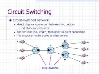
Circuit Switching Networks • End-to-end dedicated circuits between clients • Client can be a person or equipment (router or switch) • Circuit can take different forms • Dedicated path for the transfer of electrical current • Dedicated time slots for transfer of voice samples • Dedicated frames for transfer of Nx51.84 Mbps signals • Dedicated wavelengths for transfer of optical signals • Circuit switching networks require: • Multiplexing & switching of circuits • Signaling & control for establishing circuits • These are the subjects covered in this chapter
How a network grows • A switch provides the network to a cluster of users, e.g. a telephone switch connects a local community Network Access network (b) A multiplexer connects two access networks, e.g. a high speed line connects two switches
a b A d c Network of Access Subnetworks A Network Keeps Growing 1* b a 2 4 (a) Metropolitan network A viewed as Network A of Access Subnetworks 3 A c d Metropolitan (b) National network viewed as Network of Regional Subnetworks (including A) A • Very high-speed lines Network of Regional Subnetworks National & International
Chapter 4Circuit-Switching Networks Multiplexing
(a) (b) A A A A B B MUX MUX B B C C C C Multiplexing • Multiplexing involves the sharing of a transmission channel (resource) by several connections or information flows • Channel = 1 wire, 1 optical fiber, or 1 frequency band • Significant economies of scale can be achieved by combining many signals into one • Fewer wires/pole; fiber replaces thousands of cables • Implicit or explicit information is required to demultiplex the information flows. Shared Channel
Channel divided into frequency slots Guard bands required AM or FM radio stations TV stations in air or cable Analog telephone systems B f A f 0 Wu C C 0 Wu f 0 Wu B A f W 0 Frequency-Division Multiplexing (a) Individual signals occupy Wu Hz (b) Combined signal fits into channel bandwidth
A1 A2 … t 0T 6T 3T B1 B2 … t 6T 3T 0T C1 C2 … t 0T 6T 3T C2 A2 B2 … A1 C1 B1 t 0T 1T 2T 3T 4T 5T 6T Time-Division Multiplexing (a) Each signal transmits 1 unit every 3T seconds • High-speed digital channel divided into time slots • Framing required • Telephone digital transmission • Digital transmission in backbone network (b) Combined signal transmits 1 unit every T seconds
1 1 2 MUX 2 MUX . . . . . . 22 23 24 b 24 2 1 b . . . Frame 24 24 T-Carrier System • Digital telephone system uses TDM. • PCM voice channel is basic unit for TDM • 1 channel = 8 bits/sample x 8000 samples/sec. = 64 kbps • T-1 carrier carries Digital Signal 1 (DS-1) that combines 24 voice channels into a digital stream: Framing bit • Bit Rate = 8000 frames/sec. x (1 + 8 x 24) bits/frame • = 1.544 Mbps
1 DS1 signal, 1.544Mbps . . Mux 24 1 DS2 signal, 6.312Mbps . 24 DS0 . 4 DS1 Mux 4 1 DS3 signal, 44.736Mpbs . . 7 DS2 Mux 7 1 . . 6 DS3 Mux 6 DS4 signal 274.176Mbps North American Digital Multiplexing Hierarchy • DS0, 64 Kbps channel • DS1, 1.544 Mbps channel • DS2, 6.312 Mbps channel • DS3, 44.736 Mbps channel • DS4, 274.176 Mbps channel
1 2.048 Mbps . . Mux 30 1 8.448 Mbps . 64 Kbps . Mux 4 1 34.368 Mpbs . . Mux 139.264 Mbps 1 . . Mux 4 CCITT Digital Hierarchy(European Standards) • CCITT digital hierarchy based on 30 PCM channels • E1, 2.048 Mbps channel • E2, 8.448 Mbps channel • E3, 34.368 Mbps channel • E4, 139.264 Mbps channel
MUX t 2 5 4 3 2 1 5 4 3 1 Clock Synch & Bit Slips • Digital streams cannot be kept perfectly synchronized • Bit slips can occur in multiplexers Slow clock results in late bit arrival and bit slip
Muxing of equal-rate signals Pulse stuffing Pulse Stuffing • Pulse Stuffing: synchronization to avoid data loss due to slips • Output rate > R1+R2 • i.e. DS2, 6.312Mbps=4x1.544Mbps + 136 Kbps • Pulse stuffing format • Fixed-length master frames with each channel allowed to stuff or not to stuff a single bit in the master frame. • Redundant stuffing specifications • signaling or specification bits (other than data bits) are distributed across a master frame. requires perfect synch
Optical fiber link carries several wavelengths From few (4-8) to many (64-160) wavelengths per fiber Imagine prism combining different colors into single beam Each wavelength carries a high-speed stream Each wavelength can carry different format signal e.g. 1 Gbps, 2.5 Gbps, or 10 Gbps Optical deMUX Optical MUX 1 1 2 1 2 2. m Optical fiber m m Wavelength-Division Multiplexing
Example: WDM with 16 wavelengths 30 dB 1540 nm 1550 nm 1560 nm
SONET: Overview • SynchronousOptical NETwork • North American TDM physical layer standard for optical fiber communications • 8000 frames/sec. (Tframe = 125 sec) • compatible with North American digital hierarchy • SDH (Synchronous Digital Hierarchy) elsewhere • Needs to carry E1 and E3 signals • Compatible with SONET at higher speeds • Greatly simplifies multiplexing in network backbone • OA&M support to facilitate network management • Protection & restoration
MUX MUX DEMUX DEMUX Insert tributary Remove tributary MUX DEMUX ADM Insert tributary Remove tributary SONET simplifies multiplexing Pre-SONET multiplexing: Pulse stuffing required demultiplexing all channels SONET Add-Drop Multiplexing: Allows taking individual channels in and out without full demultiplexing
SONET Specifications • Defines electrical & optical signal interfaces • Electrical • Multiplexing, Regeneration performed in electrical domain • STS – Synchronous Transport Signals defined • Very short range (e.g., within a switch) • Optical • Transmission carried out in optical domain • Optical transmitter & receiver • OC – Optical Carrier
DS1 Low-speed mapping function DS2 STS-1 E1 51.84 Mbps Medium speed mapping function DS3 STS-1 44.736 OC-n STS-n STS-1 STS-1 High- speed mapping function E4 STS-1 STS-1 Scrambler E/O STS-1 STS-1 139.264 . . . . . . STS-3c MUX STS-3c High- speed mapping function ATM or POS SONET Multiplexing
SONET Equipment • By Functionality • ADMs: dropping & inserting tributaries • Regenerators: digital signal regeneration • Cross-Connects: interconnecting SONET streams • By Signaling between elements • Section Terminating Equipment (STE): span of fiber between adjacent devices, e.g. regenerators • Line Terminating Equipment (LTE): span between adjacent multiplexers, encompasses multiple sections • Path Terminating Equipment (PTE): span between SONET terminals at end of network, encompasses multiple lines
PTE PTE LTE LTE SONET terminal SONET terminal STE STE STE MUX MUX Reg Reg Reg Section Section Section Section STS Line STS-1 Path STE = Section Terminating Equipment, e.g., a repeater/regenerator LTE = Line Terminating Equipment, e.g., a STS-1 to STS-3 multiplexer PTE = Path Terminating Equipment, e.g., an STS-1 multiplexer Section, Line, & Path in SONET • Often, PTE and LTE equipment are the same • Difference is based on function and location • PTE is at the ends, e.g., STS-1 multiplexer. • LTE in the middle, e.g., STS-3 to STS-1 multiplexer.
Path Path Line Line Line Line Section Section Section Section Section Section Section Optical Optical Optical Optical Optical Optical Optical Section, Line, & Path Layers in SONET • SONET has four layers • Optical, section, line, path • Each layer is concerned with the integrity of its own signals • Each layer has its own protocols • SONET provides signaling channels for elements within a layer
SONET STS Frame • SONET streams carry two types of overhead • Path overhead (POH): • inserted & removed at the ends • Synchronous Payload Envelope (SPE) consisting of Data + POH traverses network as a single unit • Transport Overhead (TOH): • processed at every SONET node • TOH occupies a portion of each SONET frame • TOH carries management & link integrity information
810 Octets per frame @ 8000 frames/sec 90 columns 1 J0 A1 A2 J1 Order of transmission 2 B3 B1 E1 F1 D1 D3 C2 D2 H2 H3 H1 G1 9 rows B2 K1 K2 F2 D5 D6 D4 H4 D8 D9 Z3 D7 D11 D10 D12 Z4 N1 S1 M0/1 E2 3 Columns of Transport OH Synchronous Payload Envelope (SPE) 1 column of Path OH + 8 data columns Section Overhead Path Overhead Line Overhead Data STS-1 Frame • 810x64kbps=51.84 Mbps Special OH octets: A1, A2 Frame Synch B1 Parity on Previous Frame (BER monitoring) J0 Section trace (Connection Alive?) H1, H2, H3 Pointer Action K1, K2 Automatic Protection Switching
Pointer indicates where SPE begins within a frame Pointer enables add/drop capability First octet Pointer Frame k 87 Columns Synchronous payload envelope 9 Rows Last octet Pointer Frame k+1 First column is path overhead SPE Can Span Consecutive Frames
FIFO 1,000,000 bps 1,000,001 bps Stuffing in SONET • Consider system with different clocks (faster out than in) • Use buffer (e.g., 8 bit FIFO) to manage difference • Buffer empties eventually • One solution: send “stuff” • Problem: • Need to signal “stuff” to receiver
Frame k Frame k Pointer Pointer First octet of SPE First octet of SPE Stuff byte Stuff byte Frame k + 1 Frame k + 1 Pointer Pointer First octet of SPE First octet of SPE • Negative byte stuffing • Input faster than output • Send extra byte in H3 to catch up Negative & Positive Stuff (b) Positive byte stuffing Input is slower than output Stuff byte to fill gap
STS-1 STS-1 STS-1 STS-1 Map Byte Interleave STS-3 STS-1 STS-1 STS-1 STS-1 Map STS-1 STS-1 STS-1 STS-1 Map Incoming STS-1 frames Synchronized new STS-1 frames Synchronous Multiplexing • Synchronize each incoming STS-1 to local clock • Terminate section & line OH and map incoming SPE into a new STS-1 synchronized to the local clock • This can be done on-the-fly by adjusting the pointer • All STS-1s are synched to local clock so bytes can be interleaved to produce STS-n
Order of transmission 1 2 J0 A1 A2 J1 3 J0 A1 A2 J1 B3 B1 E1 F1 B3 B1 E1 F1 D1 D3 C2 D2 D1 D3 C2 D2 H1 H2 H3 G1 H1 H2 H3 G1 B2 K1 K2 F2 B2 K1 K2 F2 D5 D6 D4 H4 D6 H4 D5 D4 D8 D9 Z3 D7 D8 D9 Z3 D7 D11 D10 D12 Z4 D11 D10 D12 Z4 N1 S1 M0/1 E2 M0/1 N1 S1 E2 J0 A1 A2 J1 B1 E1 F1 B3 D1 D3 C2 D2 H1 H2 H3 G1 B2 K1 K2 F2 D5 D6 D4 H4 D8 D9 Z3 D7 D10 D11 D12 Z4 N1 S1 M0/1 E2 Octet Interleaving
J1 B3 C2 G1 F2 H4 Z3 Z4 N1 Concatenated Payloads • Needed if payloads of interleaved frames are “locked” into a bigger unit • Data systems send big blocks of information grouped together, e.g., a router operating at 622 Mbps • SONET/SDH needs to handle these as a single unit • H1,H2,H3 tell us if there is concatenation • STS-3c has more payload than 3 STS-1s • STS-Nc payload = Nx780 bytes • OC-3c = 149.760 Mb/s • OC-12c = 599.040 Mb/s • OC-48c = 2.3961 Gb/s • OC-192c = 9.5846 Gb/s Concatenated Payload OC-Nc • N x 87 columns 87N - (N/3) columns of payload (N/3) – 1 columns of fixed stuff
Chapter 4 Circuit-Switching Networks Transport Networks
Telephone Switch Telephone Switch Telephone Switch Router Router Router Transport Network Transport Networks • Backbone of modern networks • Provide high-speed connections: Typically STS-1 up to OC-192 • Clients: large routers, telephone switches, regional networks • Very high reliability required because of consequences of failure • 1 STS-1 = 783 voice calls; 1 OC-48 = 32000 voice calls;
MUX DEMUX ADM Insert tributary Remove tributary SONET ADM Networks • SONET ADMs: the heart of existing transport networks • ADMs interconnected in linear and ring topologies • SONET signaling enables fast restoration (within 50 ms) of transport connections
1 2 4 3 2 3 1 4 Linear ADM Topology • ADMs connected in linear fashion • Tributaries inserted and dropped to connect clients • Tributaries traverse ADMs transparently • Connections create a logical topology seen by clients • Tributaries from right to left are not shown
W T R Bridge Selector R T P 1+1 Linear Automatic Protection Switching T = Transmitter W = Working line R = Receiver P = Protection line • Simultaneous transmission over diverse routes • Monitoring of signal quality • Fast switching in response to signal degradation • 100% redundant bandwidth
Switch Switch W R T APS signaling T R P 1:1 Linear APS • Transmission on working fiber • Signal for switch to protection route in response to signal degradation • Can carry extra (preemptible traffic) on protection line
Switch Switch W 1 T R W ² T R … … … … W … n T R P T R APS signaling 1:N Linear APS • Transmission on diverse routes; protect for 1 fault • Reverts to original working channel after repair • More bandwidth efficient
(a) (b) a a OC-3n OC-3n b c b c OC-3n Logical fully connected topology Three ADMs connected in physical ring topology SONET Rings • ADMs can be connected in ring topology • Clients see logical topology created by tributaries
SONET Ring Options • 2 vs. 4 Fiber Ring Network • Unidirectional vs. bidirectional transmission • Path vs. Link protection • Spatial capacity re-use & bandwidth efficiency • Signalling requirements
Two-Fiber Unidirectional Path Switched Ring Two fibers transmit in opposite directions • Unidirectional • Working traffic flows clockwise • Protection traffic flows counter-clockwise • 1+1 like • Selector at receiver does path protection switching
UPSR 1 W 2 4 P W = Working Paths P = Protection Paths • No spatial re-use Each path uses 2x bw 3
UPSR path recovery 1 W 2 4 P W = Working line P = Protection line 3
UPSR Properties • Low complexity • Fast path protection • 2 TX, 2 RX • No spatial re-use; ok for hub traffic pattern • Suitable for lower-speed access networks • Different delay between W and P path
Four-Fiber Bidirectional Line Switched Ring • 1 working fiber pair; 1 protection fiber pair • Bidirectional • Working traffic & protection traffic use same route in working pair • 1:N like • Line restoration provided by either: • Restoring a failed span • Switching the line around the ring
4-BLSR 1 Equal delay W P Standby bandwidth is shared 2 4 Spatial Reuse 3
BLSR Span Switching 1 W Equal delay P • Span Switching restores failed line 2 4 Fault on working links 3
BLSR Span Switching 1 W Equal delay P • Line Switching restores failed lines 2 4 Fault on working and protection links 3