SPECTROSCOPY From Science to Science
330 likes | 483 Vues
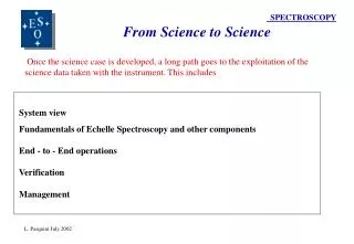
SPECTROSCOPY From Science to Science. Once the science case is developed, a long path goes to the exploitation of the science data taken with the instrument. This includes. System view Fundamentals of Echelle Spectroscopy and other components End - to - End operations Verification

SPECTROSCOPY From Science to Science
E N D
Presentation Transcript
SPECTROSCOPY From Science to Science Once the science case is developed, a long path goes to the exploitation of the science data taken with the instrument. This includes System view Fundamentals of Echelle Spectroscopy and other components End - to - End operations Verification Management L. Pasquini July 2002
SPECTROSCOPY System View 1 Astronomers are those who know how the instrument has to perform: they are the best people to provide with Technical (or at least Level 1) Requirements. .. One Instrument is not the sum of its components; it is much more; to obtain the goal prefixed the different components need to be balanced. Some additional aspects, which are peculiar to the astronomers, are: How do I want to operate the instrument ? How am I going to reduce the data ? How can I calibrate it ? ( ‘oh, that is only software’…..) L. Pasquini July 2002
SPECTROSCOPY System View 2 L. Pasquini July 2002
SPECTROSCOPY System View 3 L. Pasquini July 2002
SPECTROSCOPY Echelle Spectrographs 1 2D large detectors have made of (cross dispersed) Echelle spectroscopy the most efficient way of performing high resolution spectroscopy. A few concepts and formulae (see e.g. Gray 1996 (The observations and analysis of stellar photospheres), Schroeder 2002 (Astronomical Optics), or Born and Wolf for details on the formulae): Angular Dispersion: dß/dλ the angular difference between two rays of wavelength difference dλ emerging from the disperser. Different dispersing element have different angular dispersion laws. L. Pasquini July 2002
SPECTROSCOPY Echelle Spectrographs 2 Linear Dispersion: The linear separation on the focal plane for two rays of dλ For collimated light incident on a disperser dl/dλ = f*dß/dλ The resolution observed is NOT the disperser resolution, rather given by the width of the entrance ‘slit’ as mapped onto the spectrum formed in the focal plane of the camera. Telescope scale (Arcsec/mm) S = 206265 / f (f = telescope focal length) L. Pasquini July 2002
SPECTROSCOPY Echelle Spectrographs 3 Grating Equation:mλ = d(sinß + sin α) m = order number λ=wavelength d = groove distance α=incident angle ß=diffracted angle dß /dλ = m /d cosß Angular dispersion can be increased either by increasing the number of grooves/mm (smaller d) or by working at high orders m (Echelle spectrographs). The higher the orders, the smaller will be the FREE SPECTRAL RANGE: two wavelengths in fact will overlap as soon as mλ = (m+1) λ’ Dλ = λ’ - λ = λ/m The higher the order, the shorter is the FREE SPECTRAL RANGE. Given angular dispersion and wavelength, the larger is the number of lines/mm, the larger is the FREE SPECTRAL RANGE. L. Pasquini July 2002
SPECTROSCOPY Echelle Spectrographs 4 Without a shape, the intensity, which is the interference pattern modulated by the diffraction (blaze) pattern, will have maxima at 0 order…. Not really optimal for an astronomical spectrograph! To increase the efficiency the grating surface is blazed so to produce a the desired phase shift between the base and the edge of the grooves. (Rayleigh 1988 suggested it in 1988, first ruling in 1910!) The maximum energy is therefore moved to higher orders. The maximum intensity is produced at the angle for which the light would be reflected. That is why echelles are produced: working at high orders with the highest efficiency L. Pasquini July 2002
SPECTROSCOPY Echelle Spectrographs 5 Resolution and Aperture:(Littrow case: α=β=θ) R* φ = 206265*2B tang(δ) / D φ = arcseconds in the sky, B = spectrograph beam (on the grating), δ = echelle (blaze) angle (tang(δ) = 2 called R-2, 3 R-3, etc..) D = Telescope Diameter Where the numerator indicates the path difference of marginal rays spanning the grating. L. Pasquini July 2002
SPECTROSCOPY Echelle Spectrographs 6 Resolution and Aperture:(Littrow case) R* φ = 2B tang(δ) / D R Independent of wavelength (1st approx. R in Km/sec) R is Independent of the number of lines/mm of the echelle Larger Telescope or higher resolution: either larger Beam (costs and space), or very high Echelle angles (limits at R4, efficiency) , or smaller sky aperture (slit losses, it enhances the case of excellent seeing). With an 8M telescope, a 20 cm beam, to obtain a R* φ = 40000 an R4 is necessary. L. Pasquini July 2002
SPECTROSCOPY Echelle Spectrographs 7 Slit Projection: Given a slit of Width W and height H, and its projections on the detector W’ and H’ we find (neglecting anamorphism) : W’ = W * fcam / fcoll = (Arcsec)/206265 * ftel * fcam/fcoll W’= φ*Dtel*fcam/Dcoll (Ftel=Fcol) W’ = (Arcsec) = 206265*W’ *fcoll / (ftel*fcam) With: ftel, fcam, fcoll = focal length of telescope, camera, collimator fi = Di * Fi L. Pasquini July 2002
SPECTROSCOPY Echelle Spectrographs 8 W’ = W * fcam / fcoll = φ*Dtel*fcam/Dcoll φ= W’*fcoll / (ftel*fcam)=W’*Dcoll/Dtel*fcam With: ftel, fcam, fcoll = focal length of telescope, camera, collimator fi = Di * Fi The larger the telescope, the most difficult is to have many arcsec/pix. For a 15 microns pixel at VLT(f=120 m), Phi = 0.026 * fcoll / fcam or at most 0.2-0.3 arcsec/pixel.(trade-off between sampling, resolution, S/N ratio) Consider W’ =(Arcsec)/206265 * ftel * fcam/fcoll at most Fcoll=Ftel and Dcoll=Dcam --> W’ = Dtel*Fcam / 206265 !! With 0.015mm pixel and D=8 meter Fcam=0.39!! Independent of any optics in he middle. Arcsec/Pix on the detector is one of the few basic parameters for starting a design. Typical is to follow Nyquist criterium of projecting the slit on at least 2 detector pixels. This is independent of the disperser and of the resolution wanted, rather with the sky aperture which I want to observe and to project on the detector Again: which science ? , which is the typical seeing + image quality at the telescope ? (see e.g. AVES!) L. Pasquini July 2002
SPECTROSCOPY Echelle Spectrographs 9 Order Separation: In MOS spectroscopy, done with a pre-disperseror filter (e.g. CES, GIRAFFE) Crossdisperser Echelle : Grating: Dy = C * λb^2 + Large order separation is easily obtained, many possible choices off-the-shelves + Large size grating are available, large choice of lines/mm , blaze - Second order contamination (coverage 1 octave), sometimes efficiency Prism: Dy = C / λb + No second order contamination, nice use of detector space, high efficiency - Limited order separation, prism size Grism: Dy = C*λb^(α) with α < 2. + Nice use of detector space, transmission (geometry), no anamorphism, small camera - Size of grism, sometimes transmission, second order contamination L. Pasquini July 2002
SPECTROSCOPY Echelle Spectrographs 10 Grism as X-disperser: Harps L. Pasquini July 2002
SPECTROSCOPY Detector Characteristics Detector QE: Number photons arrived / number of electrons read Detector Noise: RON (e-/read pixels), Dark Current: (e-/physical pixel/hour) We are approaching ‘ultimate’ detector: high QE, RON<2 e-/pix, DC < 1 e-/pix/hour QE can be optimized on the spectral range of interest L. Pasquini July 2002
SPECTROSCOPY Signal-to-noise ratio S/N ratio : S/N = S/(S + nbpix* RON^2 + npix*DK + NSKY)^0.5 Poisson Noise + RON noise (binned pixel) + Dark Current (real pixel)+ SKY λ*N phot =C* Eff* Area* 10^-0.25*( mn + Aλ*Airm) (photons/Angstrom/Sec) Eff= System efficiency mn=monochromatic magnitude Aλ= Atmospheric Absorption coefficient at given wavelength. Airm= Airmass of the observation For high dispersion: Objects photons over many pixels: RON Relevant SKY/pixel can be low. ----> small aperture ---> low sky SEEING and small apertures are relevant for faint object spectroscopy! L. Pasquini July 2002
SPECTROSCOPY Signal-to-noise ratio Expected perorfmances of GIRAFFE a VLT (15,30,60,120 minutes integration): GIRAFFE has two gratings: at low resolution S/N ratio is higher because of more source photons/pixel. Note the change of slope when RON and SKY start to be relevant. For the same reason curves at different integration times are not perfectly parallel. L. Pasquini July 2002
SPECTROSCOPY Pushing the Limits Quantitative spectroscopy of stars in external galaxies Solar stars in Sagittarius, LMC To push the faint limits we need: 1) High Efficiency 2) Little SKY: a) Small Aperture b) Resolution 3) Spread of the resolution element over minimum number of pixels.. L. Pasquini July 2002
SPECTROSCOPY THE AVES CONCEPT USE AN INTERMEDIATE RESOLUTION SPECTROGRAPH BEHIND AN AO SYSTEM! Even IF AO does not provide high Strehl Ratios in V-R-I, still concentrate flux.. Minimize aperture ( 0.3 arcseconds): minimize sky, small instrument (Pasquini et al. 1998, Pallavicini et al. 2000 SPIE conference) L. Pasquini July 2002
SPECTROSCOPY THE AVES CONCEPT CROSSDISPERSED ECHELLE SPECTROGRAPH OPTIMIZED FOR RED (500-1000 nm): Coatings, CCD ! 79 lines/mm R2 echelle: Most efficient ever built, coated PRISM crossdisperser: Very efficient! R = 15000 with a 0.3 arcsecond aperture at VLT and only a 5 cm beam! 0.1 arcseconds/pixel (3 pixel sampling) L. Pasquini July 2002
SPECTROSCOPY THE AVES DESIGN L. Pasquini July 2002
SPECTROSCOPY THE AVES PERFORMANCES Overall efficiency assumed 0.16 L. Pasquini July 2002
SPECTROSCOPY Fibres The fibres work because of total reflection between the fibre interior and the external cladding. No polarization information carried on, good scrambling, good transmission Fibre core: the real aperture (50 microns and larger) L. Pasquini July 2002
SPECTROSCOPY Fibres Transmission Fibre transmission: Typically very good in the red, (dry fibres) , poor in Blue - UV, although can be used for short length (wet fibres) To minimize losses a lot of care must go into Fibre Coupling: Coupling between fibres and optical surfaces (e.g. microlenses) L. Pasquini July 2002
SPECTROSCOPY Fibres FRD Focal Ratio Degradation: The F/ratio degrades to typically a faster beam (e.g F/6-F/4)- This has to be taken into account when designing an instrument.. To avoid vignetting , best case around F/3.. L. Pasquini July 2002
SPECTROSCOPY Fibres Scrambling Scrambling: passing through the fibres the light ‘forget’ the input spatial distribution to a large extent. This is a very important characteristic for some applications, such as accurate radial velocities studies. L. Pasquini July 2002
SPECTROSCOPY End to End Operations Even if instrument concept may have not change dramatically, Operations did! User - Community Visitor -Service Archive ? Calibrations ! Calibration Plan Data Reduction - Pipelines Instrument and Data quality control L. Pasquini July 2002
SPECTROSCOPY Quality Control User - Community Visitor - Service Archive ? Calibrations ! Calibration Plan Data Reduction - Pipelines Instrument and Data quality control L. Pasquini July 2002
SPECTROSCOPY Quality Control L. Pasquini July 2002
SPECTROSCOPY Verification 1 Technical Specs need to be VERIFIED, through a VERIFICATION MATRIX remember that good technical specs. REQUIRES numbers ! These are done through ACCEPTANCE PROCEDURES and COMMISSIONING PERIOD(S). Following a COMMISSIONING PLAN aimed at verifying the Performances and assess the instrument performances and its operations. L. Pasquini July 2002
SPECTROSCOPY Verification 2 L. Pasquini July 2002
SPECTROSCOPY Management Tools Project Management Tools help to ensure that the project is finished (do not guarantee..) a) Fulfilling the technical requirements (QUALITY) b) Within the allocated funds and manpower (BUDGET) c) In the specified period (SCHEDULE) As somebody said : Pick up TWO !! L. Pasquini July 2002
SPECTROSCOPY Management Tools L. Pasquini July 2002