X-rays
X-rays. Ouch!. X-rays. X-rays are produced when electrons are accelerated and collide with a target Bremsstrahlung x-rays Characteristic x-rays X-rays are sometimes characterized by the generating voltage 0.1-20 kV soft x-rays 20-120 kV diagnostic x-rays

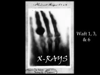
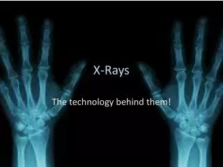
X-rays
E N D
Presentation Transcript
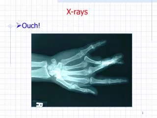
X-rays • Ouch!
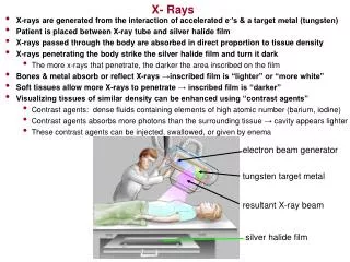
X-rays • X-rays are produced when electrons are accelerated and collide with a target • Bremsstrahlung x-rays • Characteristic x-rays • X-rays are sometimes characterized by the generating voltage • 0.1-20 kV soft x-rays • 20-120 kV diagnostic x-rays • 120-300 kV orthovoltage x-rays • 300 kV – 1 MV intermediate energy x-rays • > 1MV megavoltage x-rays
Bremmstrahlung • Bremsstrahlung x-rays occur when electrons are (de)accelerated in the Coulomb field of a nucleus
Bremsstrahlung • The power radiated from an accelerating charge is given by Larmor’s equation • In the case of an electron in the Coulomb field of a nucleus
Bremsstrahlung • The probability of bremsstrahlung goes as Z2, hence high Z targets are more effective than low Z • The energy of the x-rays varies from zero to the maximum kinetic energy of the electron (x-ray tube kVp) • The energy spectrum from a thick target goes as 1/E but inherent (1mm Al eq) plus additional (few mm Al) filtration removes the lower energy x-rays • Here I am referring to diagnostic x-rays
Bremsstrahlung • The unfiltered energy spectrum is approximately given by Kramer’s law which was an early application of quantum mechanics
Characteristic x-rays • After excitation, ions with a vacancy in their inner shell can de-excite • Radiatively through x-ray fluorescence • Non-radiatively through the emission of Auger electrons
Characteristic X-rays • Thus an x-ray spectrum will also show characteristic x-rays arising from L to K and M to K transitions after ionization of a K electron • Usually transitions to higher shells absorbed by the filtration or are not x-rays
Characteristic X-rays • The probability of K shell fluorescence increases with Z
Characteristic X-rays • Sometimes the characteristic x-rays are emphasized using the same material for target and filter • Characteristic x-rays from molybdenum are effective in maximizing contrast in mammography
Characteristic X-rays • Mo target, filter, and result
Directionality • For MeV electrons, bremsstrahlung x-rays are preferentially emitted in the electron’s direction • For keV electrons, bremsstrahlung x-rays are emitted at larger angles • Characteristic x-rays are emitted isotropically since there is no angular correlation between the incident electron that causes the ionization and the fluorescent photon
X-ray Tube • A simplified x-ray tube (Coolidge type) shows the idea behind most x-ray tubes today
X-ray Tube • In addition to bremsstrahlung and characteristic x-ray production, electrons also loose energy through collisions • Collision losses dominate in this energy region • For 100 keV electrons in W • Thus >99% of the electron energy goes into heating the target rather than x-rays • Removing heat from the anode in a vacuum is an issue
X-ray Tube • Efficiency of x-ray production depends on the tube voltage and the target material • W (Z=74) in this example
X-ray Tube • X-ray tubes
X-ray Tube • More detail
X-ray Tube • Housing for shielding (Pb) and cooling (oil)
X-ray Tube • More detail
X-ray Tube • The main parts of the x-ray tube are • Cathode/filament • Typical electron current is 0.1-1.0 A for short exposures (< 100 ms) • Anode/target • Glass/metal envelope • Accelerating voltage • Typical voltage is 20-150 kVp
Cathode • Cathode consists of • Low R tungsten wire for thermionic emission • Tungsten has a high melting point (3370C) and minimum deposit on the glass tube • Tube current is controlled by varying the filament current which is a few amps • A focusing cup • Uses electric field lines to focus the electrons • Typically there are two filaments • Long one: higher current, lower resolution • Large focal spot • Short one: lower current, higher resolution • Small focal spot
Cathode • Dual focus filament is common
Anode • Usually made of tungsten in copper because of high Z and high melting point • Molybdenum and rhodium used for soft tissue imaging • Large rotating surface for heat distribution and radiative heat loss • Rotation of 3k-10k revolutions/minute • Resides in a vacuum (~10-6 torr) • Thermally decoupled from motor to avoid overheating of the shaft • Target is at an tilted angle with respect to axis • Bremsstrahlung is emitted at ~ right angles for low energy electrons • Determines focal spot size
Anode • The heating of the anode limits the voltage, current, and exposure time • An exposure rating chart gives these limits
Anode • Power = V x I (watts) • Energy = Power x time = V x I x s (joules) • HU (Heating Unit) ~ J • Damaged anodes
Angle ‘ Angle Actual focal spot size Actual focal spot size Incident electron beam width Incident electron beam width Increased apparent focal spot size Apparent focal spot size Film Film Anode • The angle determines the projected focal spot • The smaller the angle the better the resolution • Typically 7-20 degrees
X-rays • The energy of the photons depends on the electron energy (kVp) and the target atomic number Z • The number of photons depends on the the electron energy (kVp), Z, and the beam current (mA) • A typical number / area is ~ 1013 / m2 • About 1% will hit the film ~ 1011 / m2 • Absorption and detection efficiency will further reduce this number
X Ray tube Collimator Beam Soft tissue Patient Air Bone Table Grid AEC detectors Cassette Automatic Exposure Control • AEC detectors can ionization chambers or solid-state detectors
Automatic Exposure Control • Most modern x-rays machines are equipped with automatic exposure control also called a phototime • The AEC sets the technical parameters of the machine (kV, mA, time, …) in order to avoid repeated exposures • AEC is used to keep the radiographic quality (film density) equal on all patients • AEC detectors can be ionization chambers or solid state detectors
Grid • To reduce the number of secondary scattered photons making it to the film, a grid between the patient and film is used
Grid • Details • Grid bars are usually lead whereas the grid openings are usually made of aluminum or carbon • Grid thickness is typically 3 mm • Grid ratio is H/W and 10/1 is typical • Grid frequency of 60 lines / cm is typical • B/W/H on the figure might be 0.045, 0.120, 1.20 in mm • The Bucky factor is the entrance exposure w/wo the grid while achieving the same film density – 4 is average
Accelerating Voltage • The potential difference between cathode and anode must be generated by 60 Hz 220V AC power • High voltages are produced using a transformer
Accelerating Voltage • Electrons are accelerated when the filament is at a negative potential with respect to the target • Diode circuits can be used to provide rectification (AC to DC voltage) • Three phase power (6 pulse or 12 pulse) can be used to reduce ripple • Constant potential operation can be achieved by using constant potential (voltage regulations) or high frequency x-ray generators
Half-wave Rectifier • Not very efficient
Full-wave Bridge Rectifier • This circuit allows the entire input waveform to be used
Single phase single pulse kV ripple (%) 100% Single phase 2-pulse 13% Three phase 6-pulse 4% Three phase 12-pulse Line voltage 0.01 s 0.02 s Accelerating Voltage
Images • Analog radiography • Film based – still widely used • Fluorescent screens are used to convert x-rays into visible light that is then recorded on film • Screens are more efficient at stopping x-rays than the film (CaWO4 or Gd2O2S:Tb or other rare earth)
Analog Radiography • The film itself has excellent spatial resolution but • Film detects 0.65% of incident x-ray energy • Gd2O2S detects 29.5% of incident x-ray energy • Thus using phosphor screens greatly reduces the radiation dose to the patient • And also reduces load on the x-ray tube
Analog Radiography • There are two efficiency considerations • Absorption efficiency or QDE • Fraction of incident x-rays that interact with the screen • Depends on kVp and screen thickness • Gd2O2S has a QDE of ~ 60% for 80 kVp beam, 20 cm patient, 120 mg/cm2 screen thickness
Analog Radiography • Conversion efficiency • Fraction of absorbed x-ray energy that is emitted as light • 5% for CaWO4 • 15% for Gd2O2S • 50,000 eV x 0.15 = 7500 eV • 7500 eV / 2.7 eV = 2800 photons produced per absorbed x-ray • 50-90% reduction in photon diffusion to film
Film Body Dark Light X-Ray source Analog Radiography • Film is an emulsion containing silver-halide grains (AgBr and AgI) coated on mylar
Film Badge • A film badge consists of a photographic film with various filters • The film is a gelatin emulsion containing silver-halide grains (95% AgBr and 5% AgI) on a supporting material • Grain diameter is ~ 1mm
Film Badge • The film is exposed by light by • An electron is released from Br- and moves about the 1m diameter crystal • The electron may be captured by a trap such as a crystal imperfection or AgS speck • The trapped electron attracts mobile Ag+ ions where it is subsequently neutralized • Additional Ag atoms are formed by repeated trapping and neutralization • These Ag atoms are called a latent image center • The developing process effectively amplifies this process turning the grains with latent image centers into a visible silver deposit