Download
1 / 1
70 likes | 785 Vues
Hydraulic head = 25 cm. Hydraulic head =50 cm. Figure 1 Typical geometry and finite element mesh used for the HYDRUS-2D simulations along with typical predicted water content profiles. Hydraulic head = 100 cm. Hydraulic head = 200 cm.

E N D
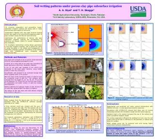
Hydraulic head = 25 cm Hydraulic head =50 cm Figure 1 Typical geometry and finite element mesh used for the HYDRUS-2D simulations along with typical predicted water content profiles Hydraulic head = 100 cm Hydraulic head = 200 cm Figure 3 Measured and predicted water contents five days after initiating irrigation. Figure 2 Predicted water content profiles for A. soil texture, B. installation depth, and C. evaporation rate Soil wetting patterns under porous clay pipe subsurface irrigation A. A. Siyal1 andT. H. Skaggs2 1Sindh Agriculture University, Tandojam, Sindh, Pakistan 2U.S Salinity Laboratory, USDA-ARS, Riverside, CA, USA • Introduction: • To minimize evaporation and percolation losses, subsurface irrigation systems are being used in many arid and semi arid regions of the world. • Subsurface irrigation with clay pipes involves burying porous clay pipes in the ground and supplying water to pipes so that it seeps into the soil and root zone. • Optimizing the performance of porous clay pipe subsurface irrigation requires the development of guidelines and design criteria for system management and installation. • To investigate relationships among design parameters in clay pipe irrigation systems, and to assess the utility of using simulation in the design and management ofsubsurface irrigation systems, simulations of soil wetting made with HYDRUS-2D were compared with experimental data. Methods and Materials Clay pipes with a length of 40 cm and an inside diameter of 10 cm were prepared and baked in a kiln. A trench 20 m long and 43 cm deep was excavated at Sindh Agriculture University, Tandojam, Pakistan A run of clay pipe was installed in the trench and connected to the steel water mainline, using rubber tubing to make the connection. Groundwater was pumped to an overhead storage tank which supplied water to the system. After five days of the continuous supply of water to pipe at a hydraulic head of200 cm, soil samples were collected from the depths 0, 15, 30, 45, 60, 75 and 90 cm at distances 15, 30 and 45 cm from the pipe center; the gravimetric soil water content of each soil sample was measured. Wetting patterns for hydraulic heads of 100, 50 and 25 cm were also obtained after five days of irrigation. The texture of the was loam with bulk density ranging from 1.25 to 1.30 g cm‑3. Simulation of data Water seepage from the buried pipe into the soil was simulated using the HYDRUS-2D software package (Simunek et al., 1999). A finite element mesh was created with the axis of symmetry along the left edge. The flow domain (50 cm x 100 cm) comprised two materials, a 1.5-cm thick layer along the curved boundary representing the pipe, and the remainder of the domain representing the assumed homogeneous soil material. Soil hydraulic parameters estimated with HYDRUS-2D were θr = 0.078, θs= 0.43, Ks = 24.96 cm d-1, α = 0.036 cm-1, n = 1.56 and ℓ= 0.5. Ks for the pipe material was measured as 0.05 cm d-1 Conclusions: Experimental and predicted soil water content distributions with HYDRUS-2D were in close agreement with the observed. Simulations with HYDRUS-2D showed that there was an inverse relationship between the installation depth and the lateral spacing, Hydraulic head in the system increased the size of the wetted zone under considered hydraulic heads The surface evaporation affected the wetting front only near the soil surface while there was no difference in the geometry of wetted zone below the surface. Wider wetted zones can be achieved with soils having higher unsaturated hydraulic conductivities References: Simunek, J., Sejna, M., and van Genuchten, M. Th. (1999). ‘‘The HYDRUS-2D software package for simulating the two-dimensional movement of water, heat, and multiple solutes in variably-saturated media.’’ IGWMC-TPS 53, Version 2.0, International Ground Water Modeling Center, Colorado School of Mines, Golden, CO Acknowledgments The Higher Education Commission (HEC), Pakistan, is gratefully acknowledged for funding the project “Use of subsurface irrigation system to meet the water crisis in the country” under the National Research Program for Universities (NRPU).