Download
1 / 10
100 likes | 618 Vues
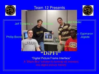
Team 12 Presents <- Bill Kreider Jeff Turkstra -> Gnomes | / <- Egomaron Jegede Phillip Boone -> A “Black Box” solution to turning old monitors into digital picture frames “DiPFI” “ Di gital P icture F rame I nterface” DiPFI Features

E N D
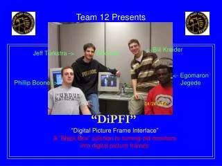
Team 12 Presents <- Bill Kreider Jeff Turkstra -> Gnomes | \/ <- Egomaron Jegede Phillip Boone -> A “Black Box” solution to turning old monitors into digital picture frames “DiPFI” “Digital Picture Frame Interface”
DiPFI Features • Provides a “networked VGA controller” to display pictures on any compatible VGA device • Image data provided via Ethernet to Rabbit Microcontroller. • VGA display is done via Epson controller interfacing with a 4MB EDO DRAM memory chip. • Address/Data Multiplexing achieved via a PLD “hack” • Epson driven by 25.175 MHz oscillator • Display controlled by on-device pushbuttons and remote control • IR remote control allows product to be placed out of reach • Status LEDs indicate transmission of a picture
Motivation • Idea originated as a “Digital Picture Frame” (with onboard LCD) • Possible uses included a replacement for concert band sheet music and a generic digital photo album • Unfortunately, reasonably large LCD’s are expensive • Decided to kill the LCD and interface with any VGA-compatible device • Made device more flexible, as well as significantly reducing cost
DiPFI Block Diagram Power Supply 9V DRAM Network PC Digital 3.3V Analog 3.3V Digital 5V Ethernet SONY IR Receiver & Decoder EPSON Graphics Controller VGA Output Rabbit Microprocessor DataBus DATA [0:15] ADDR [0:20] Switches/LEDs PLD’s (Data and Address Multiplexing) Reset Controller
DiPFI Realization Pushbuttons | \/ Rabbit Module | \/ 9V Input -> <- Ethernet Input VGA Output -> DRAM -> EPSON -> <- PLDs /\ | IR Receiver /\ | LEDs
Design challenges • Epson graphics controller, with 128 pins and 2mil spacing between each pad (rather small) • Lack of enough pins to directly interface with a 21-bit address bus & separate 16-bit data bus • Solved with PLD’s • Finding appropriate parts for each required function • DRAM especially • Software for PC and Rabbit
Why You’re in 270/362 • (with respect to this project) • PLD’s • Programmed using a language similar to ABEL and the Dataman programmer • Are basically a mode-controlled series of flip-flops • Microcontroller Interfacing • You’ll learn this in ECE 362 • Incredibly useful in terms of programming the Rabbit as well as interfacing with the Epson graphics controller • Addressing schemes • Provides necessary insight for interfacing with Epson/DRAM data and address busses • Timing analysis • Required to interface with just about any device • Ability to interpret device data sheets • Lot’s and lot’s of data sheets • Digital logic analyzers • Incredibly useful and reassuring
? Questions ? DiPFI