Smart antennas and MAC protocols in MANET
520 likes | 951 Vues
Smart antennas and MAC protocols in MANET. Lili Wei 2004-12-02. Contents. Smart antennas – basic concepts and algorithms Background knowledge System model Optimum beamformer design Adaptive beamforming algorithms DOA estimation method

Smart antennas and MAC protocols in MANET
E N D
Presentation Transcript
Smart antennas and MAC protocols in MANET Lili Wei 2004-12-02
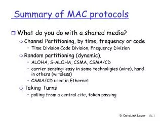
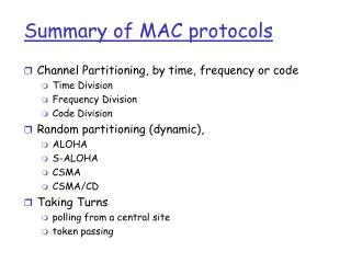
Contents • Smart antennas – basic concepts and algorithms • Background knowledge • System model • Optimum beamformer design • Adaptive beamforming algorithms • DOA estimation method • Schemes using directional antennas in MAC layer of ad hoc network • Vaidya scheme1 • Vaidya scheme2 • Nasipuri scheme • Bagrodia scheme
Background Knowledge Basic challenge in wireless communication: ---- finite spectrum or bandwidth Multiple access schemes: • FDMA • TDMA • CDMA
SDMA • Spatial Division Multiple Access ---- Uses an array of antennas to provide control of space by providing virtual channels in an angle domain
Directional Antennas • Smart antenna • Sectorised antenna • 1) switched beam system • Use a number of fixed beams • Select one of several beams to enhance receive signals • 2) adaptive array system • Be able to change its antenna pattern dynamically;
System Model • Uniform Linear Array of M elements d
System Model Narrow Band array processing Assumption: Array response vector
System Model The Beam-former Structure
A simple example Design a beamformer with unit response at 600 and nulls at 00, -300, -750
Optimum Beamformer Design Signal in AWGN and Interference
Optimum Beamformer Design Under different criterions • Maximum SINR beamformer • Mean-Square-Error optimum beamformer
Optimum Beamformer Design Under different criterion • Minimum-Variance-Distortionless-Response beamformer • Maximum Likelihood optimal beamformer
Practical Issues Issues • In practice, neither R nor RI+N is available to calculate the optimal weights of the array; • In practice, direction of arrival (DOA) is also unknown. Solution • Adaptive beamforming algorithms– the weights are adjusted by some means using the available information derived from the array output, array signal and so on to make an estimation of the optimal weights; • DOA estimation methods
Adaptive Beamforming Algorithms Block diagram of adaptive beamforming system
Adaptive Beamforming Algorithms • SMI Algorithm (Sample Matrix Inverse) • LMS Algorithm (Least Mean Square) • RLS Algorithm (Recursive Least Square) • CMA (Constant Modulus Algorithm)
Adaptive Beamforming Algorithms Estimate R using N samples: 1. SMI Algorithm (Sample Matrix Inverse) Use matrix inversion lemma: Then:
Adaptive Beamforming Algorithms 2. LMS Algorithm (Least Mean Square) According to orthogonality principle (data| error) of MMSE beamformer: Solution: • Need training bits and calculate the error between the received signal after beamforming and desired signal; • The step size u decides the convergence of LMS algorithm; • Based on how to choose u, we have a set of LMS algorithm, “unconstraint LMS”, “normalized LMS”, “constraint LMS”.
Adaptive Beamforming Algorithms 3. RLS Algorithm (Recursive Least Square) Given n samples of received signal r(t), consider the optimization problem—minimize the cumulative square error Solution: • In some situation LMS algorithm will converge with very slow speed, and this problem can be solved with RLS algorithm.
Adaptive Beamforming Algorithms 4. CMA (Constant Modulus Algorithm) Assume the desired signal has a constant modulus, the existence of an interference causes fluctuation in the amplitude of the array output. Consider the optimization problem: Solution: • This is a blind online adaptation, i.e., don’t need training bits • CMA is useful for eliminating correlated arrivals with different magnitude and is effective for constant modulated envelope signals such as GMSK and QPSK
DOA Estimation Method • MF Algorithm (Matched Filter) • MVDR Algorithm • MUSIC Algorithm (MUltiple SIgnal Classification)
DOA Estimation Method • MF Algorithm (Matched Filter) The total output power of the conventional beamformer is: • The output power is maximized when • The beam is scanned over the angular region say,(-900,900), in discrete steps and calculate the output power as a function of AOA • The output power as a function of AOA is often termed as the spatial spectrum • The DOA can be estimated by locating peaks in the spatial spectrum • This works well when there is only one signal present • But when there is more than one signal present, the array output power contains contribution from the desired signal as well as the undesired ones from other directions, hence has poor resolution
DOA Estimation Method 2. MVDR Algorithm This technique form a beam in the desired look direction while taking into consideration of forming nulls in the direction of interfering signals. Solution: • By computing and plotting pMVDR over the whole angle range, the DOA’s can be estimated by locating the peaks in the spectrum • MVDR algorithm provides a better resolution when compared to MF algorithm • MVDR algorithm requires the computation of a matrix inverse, which can be expensive for large arrays
DOA Estimation Method Comparison of resolution performance of MF and MVDR algorithms Scenario: Two signals of equal power at SNR of 20dB arrive at a 6-element uniformly spaced array at angles 90 and 100 degrees, respectively
DOA Estimation Method 3. MUSIC Algorithm (MUltiple SIgnal Classification) MUSIC is a high resolution multiple signal classification technique based on exploiting the eigenstructure of the input covariance matrix. Step 1: Collect input samples and estimate the input covariance matrix Step 2: Perform eigen decomposition
DOA Estimation Method 3. MUSIC Algorithm (MUltiple SIgnal Classification) Step 3: Estimate the number of signals based on the fact : • The first K eigen vectors represent the signal subspace, while the last M-K eigen vectors represent the noise subspace • The last M-K eigen values are equal and equal to the noise variance find the D smallest eigen values that almost equal to each other Step 4: Compute the MUSIC spectrum find the largest peaks of Pmusic to obtain estimates of DOA
DOA Estimation Method Comparison of resolution performance of MVDR and MUSIC Scenario: Two signals of equal power at SNR of 20dB arrive at a 6-element uniformly spaced array at angles 90 and 95 degrees, respectively
Summary of Part I • System model • Optimum beamformer design • Adaptive beamforming algorithms 1) SMI 2) LMS 3) RLS 4) CMA • DOA estimation method 1) MF 2) MVDR 3) MUSIC
Part II:Schemes using directional antennas in MAC layer of ad hoc network
RTS/CTS mechanism in 802.11 A B C D E RTS RTS CTS CTS DATA DATA ACK ACK
RTS/CTS mechanism in 802.11 • Nodes are assumed to transmit using omni-directional antennas. • Both RTS and CTS packet contain the proposed duration of data transmission • The area covered by the transmission range of both the sender(node B) and the receiver (node C) is reserved during the data transfer • This mechanism reduce collisions due to the hidden terminal problem • However, it waste a large portion of network capacity.
Vaidya Scheme 1 Assumption: • Each node knows its exact location and the location of its neighbors • Each node is equipped with directional antennas • If node X received RTS or CTS related to other nodes, then node X will not transmit anything in that direction until that other transfer is completed • That direction or antenna element would be said to be “blocked” • While one directional at some node be blocked, other directional at the same nodes may not be blocked, allowing transmission using the unblocked antenna
Vaidya Scheme 1 A B C D E DRTS OCTS OCTS DRTS OCTS OCTS DATA DATA ACK ACK
Vaidya Scheme 1 • Utilize a directional antenna for sending the RTS (DRTS), whereas CTS are transmitted in all directions (OCTS). • Data and ACK packets are sent directionally. • Any other node that hears the OCTS only blocks the antenna on which the OCTS was received.
A possible scenario of collisions A B C D DRTS DRTS OCTS OCTS DATA DRTS ACK
Vaidya Scheme 2 • A node uses two types RTS packets: DRTS and ORTS according to the following rules: • 1) if none of the directional antennas at node X are blocked, then node X will send ORTS; • 2) otherwise, node X will send a DRTS provided that the desired directional antenna is not blocked.
Vaidya Scheme 2 F A B C D ORTS ORTS OCTS DRTS OCTS DATA ACK
Performance 5 10 15 20 25 Simulation mesh Topology (5X5) 4 9 14 19 24 3 8 13 18 23 2 7 12 17 22 1 6 11 16 21
Nasipuri Scheme • Node A that wishes to send a data packet to B first sends an omni-directional RTS packet • Node B receives RTS correctly and responds by transmitting a CTS packet, again on all directions. • In the meanwhile, B can do DOA estimation from receiving RTS packet • Similarly, node A estimates the direction of B while receiving the CTS packet. • Then node A will proceed to transmit the data packets on the antenna facing the direction of B.
Nasipuri Scheme CTS CTS 3 4 B 2 1 CTS CTS RTS RTS Data 3 4 A 2 1 RTS RTS
Bagrodia Scheme Directional Virtual Carrier Sensing(DVCS) • Three primary capabilities are added to original 802.11 MAC protocol for directional communication with DVCS: 1) caching the Angle of Arrival (AOA) 2) beam locking and unlocking 3) the use of Directional Network Allocation Vector (DNAV)
Bagrodia Scheme • 1. AOA caching • Each node caches estimated AOAs from neighboring nodes whenever it hears any signal, regardless of whether the signal is sent to it or not • When node X has data to send, it searches its cache for the AOA information, if the AOA is found, the node will send a directional RTS, otherwise, the RTS is send omni-directionally. • The node updates its AOA information each time it receives a newer signal from the same neighbor. • It also invalidates the cache in case if it fails to get the CTS after 4 directional RTS transmission.
Bagrodia Scheme (2)CTS (3)Data • 2. Beam locking and unlocking A B (4)ACK B (1)RTS • When a node gets an RTS, it locks its beam pattern towards the source to transmit CTS • The source locks the beam pattern after it receives CTS . • The beam patterns at both sides are used for both transmission and reception, and are unlocked after ACK is completed.
DNAV(300) DNAV(3000) DNAV(750) Bagrodia Scheme • 3. DNAV setting • DNAV is a directional version of NAV(used in the original 802.11 MAC), which reserves the channel for others only in a range of directions. • In the fig: • Three DNAVs are set up towards 300, 750 and 3000 with 600 width. • Until the expiration of these DNAVs, this mode cannot transmit any signals with direction between 0-1050 or 270-3300 , but is allowed to transmit signals towards 105-2700 and 330-3600 Available directions for transmission
Bagrodia Scheme • A network situation where DVCS can improve the network capacity with DNAVs A C E F D B
Bagrodia Scheme • Performance
Summary of Part II Comparison of four schemes
Conclusion • smart antenna is a technology for wireless systems that use a set of antenna elements in an array. The signal from these antenna elements are combined to form a movable beam pattern that can be steered to a desired direction • smart antennas enable spatial reuse and they increase the communication range because of the directivity of the antennas • smart antennas can be beneficial for wireless ad hoc networks to enhance the capacity of the network • To best utilize directional antennas, a suitable MAC protocol must be designed • If the locations are unknown , DOA estimation may be needed before sending directional signals