Download

1 / 27
270 likes | 377 Vues
Transformer is a novel loosely-coupled, functional-driven full-system simulator for multicore architectures, addressing the limitations of tightly-coupled designs that typically hinder extensibility and cycle-accuracy. By utilizing an architecture-independent interface between the functional model (FM) and the timing model (TM), Transformer ensures reliable cycle-accuracy and allows for parallel processing of FM and TM, boosting performance. This paper presents the concept, implementation, and evaluation of Transformer, providing insights into the challenges and solutions for multicore simulation.

E N D
Transformer: A Functional-Driven Cycle-Accurate Multicore Simulator 黃 翔 Dept. of Electrical Engineering National Cheng Kung University Tainan, Taiwan, R.O.C 2013.05.27
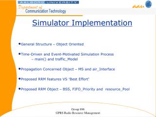
Abstract • State-of-the-art multicore simulators either • lack good extensibility due to their tightly-coupled design between functional model (FM) and timing model (TM), or • cannot guarantee cycle-accuracy. • We propose a loosely-coupled functional-driven full-system simulator for multicore, namely Transformer. • To ensure extensibility and cycle-accuracy, Transformer • leverages an architecture-independent interface between FM and TM and • uses a lightweight scheme to detect and recover from execution divergence between FM and TM. • Moreover, the loosely-coupled design also removes the complex interaction between FM and TM and opens the opportunity to parallelize FM and TM to improve performance.
1.Introduction (1/3) • There are two basic models in a full-system simulator: • functional model (FM), which provides a full-system execution environment to execute operating systems and applications and collects the resulted instruction flow and data access information; • timing model (TM), which simulates micro-architectural behavior of the instruction flow generated by FM. • FMs and TMs are usually tightly-coupled together in a full-system simulator and it is usually hard to extend new FMs or TMs in the simulator.
1.Introduction (2/3) • There is actually a good reason to take the tightly-coupled design in current mainstream full-system multicore simulators. • to guarantee cycle-accuracy such as faithful instruction execution behavior and timing • In each cycle, TM advises FM on which instruction FM should execute; • FM will also report to TM with information regarding the executed instruction, to let TM maintain correct architecture states and timing information. • Such a tightly-coupled and complex interaction between TM and FM limits both extensibility and performance of full-system simulators. • Though there have been some efforts in trying to explore a loosely-coupled design for multicore simulators [7, 6], their solutions cannot guarantee cycle-accuracy and there is no implemented prototype for multicore simulators.
1.Introduction (3/3) • In this paper, we first present a comprehensive study on the limiting factors that lead to execution divergence between FM and TM. • Based on the above analysis, we propose Transformer, a loosely-coupled, functional-driven simulation scheme for full-system multicore simulation. • We have implemented Transformer based on GEMS [9], a widely-used tightly-coupled simulator, and parallelize FM and TM to achieve better performance.
2.1Limitations with a Tightly-coupled Design (1/2) • To achieve cycle-accuracy, existing full-system multicore simulators usually exploit a tightly-coupled timing-driven design. • As shown in Figure 1, in each cycle, • TM directs FM with which instructions should be executed and • FM feeds back the executed results to TM to maintain correct architecture states and timing. • TM has to simulate part of the functional model so as to direct the execution of FM. Figure 1: Tightly-coupled Functional and Timing.
2.1Limitations with a Tightly-coupled Design (2/2) • Such a tightly-coupled and complex interaction between FM and TM makes it very difficult to extend a new FM or TM into those simulator frameworks. • In addition, the complex interaction in current tightly-coupled design limits simulation speed. • To illustrate this problem, we profile the execution proportion of FM, TM and their interactions. • to support TM, FM has to execute in instruction-by-instruction model instead of fast binary translation to provide execution information to TM
2.2Factors to Cycle-Accuracy (1/4) • To gain insight into possible solutions to loosely-coupled cycle-accurate design, we study the factors leading to execution divergence between FM and TM. • branch misprediction • shared data access order • interrupt/exception handling • shared page access order
2.2Factors to Cycle-Accuracy (2/4) • Branch misprediction: • In modern architectures, branch prediction is usually exploited in the pipeline design to avoid stall caused by branch instructions. • The branch could be mispredicted to execute a wrong path in TM. • However, FM always executes the instructions on the correct path, leading to execution divergence with actual architectural execution (i.e., TM). • Shared data access order: • In parallel applications, not all shared data are protected by lock operations to achieve some harmless operations. • Therefore, FM may execute a different write/read order compared with that of TM, which will diverge the execution path.
2.2Factors to Cycle-Accuracy (3/4) • Interrupt/exception handling: • Interrupt or exception is similar to branch misprediction. • TM handles the interrupt or exception in the commit stage after squashing the pipeline. • Before that, TM will fetch instructions from the wrong path, i.e., next program counter (PC) instead of the interrupt/exception handler code. • However, FM directly simulates the interrupt/exception handling path, which leads to execution path divergence. • Shared page access order: • The divergence will take place under two conditions. • First, two memory operations in different threads may access data within the same page. • Second, two pages accessed by two data accesses might be mapped to the same entry in the page table.
2.2Factors to Cycle-Accuracy (4/4) • Although these factors would lead to execution divergence between FM and TM, they occur rarely. • To illustrate this problem, we profile the occurrence proportion of each divergence factor in the total execution. • As the data shown in Table 1, the total proportion occurs less than 1%. • Therefore, in most cases, there is no execution divergence between FM and TM. • This opens the opportunity to use a loosely-coupled design that may result in better extensibility to support other FMs or TMs and superior performance due to possible parallelization. Table 1: Proportion of path diversities.
3. The Transformer framework (1/2) • The overall Transformer framework works as shown in Figure 2. Figure 2: The Transformer framework.
3. The Transformer framework (2/2) • In Transformer, FM in most cases generates the architecture- independent instruction and data flow information (e.g., pipeline dependence, memory access address) to TM. • TM simulates the detailed micro-architecture using instruction and data information provided by FM. • When a divergence factor is detected, different strategies (roll back FM and create a wrong-path FM) are applied to revise the divergence execution.
3.1 Divergence Detection (1/5) • To guarantee cycle accuracy in a loosely-coupled design, the first thing is to detect when and where an execution divergence occurs. • Among the four factors, it is easier to detect branch misprediction and interrupt or exception handling. • For branch misprediction, we can detect the divergence through checking whether the target address of a branch instruction in TM is the same as that in FM. • For interrupt or exception handling, whenever it occurs, a divergence happens.
3.1 Divergence Detection (2/5) • Shared Data Access Order: • As an important factor affecting cycle-accuracy, prior work [6] detects violation in shared data access order through checking whether the loaded values of shared memory between FM and TM are the same. • Since the loaded value may be affected by a faraway prior store instruction or two store instructions may have written the same value, the order violation information may have already been lost when the loaded value is detected to be violated. • To overcome this problem, we use a more accurate method: when FM executes instructions, it records its access order for each shared datum. • When TM commits the memory instruction, it checks whether its access order is the same as that of FM. If it is different, a divergence occurs. • To achieve this, we design a data structure called Memory Access Table (MAT) to efficiently record and check the shared data access order. • As shown in Figure 3.
3.1 Divergence Detection (3/5) • Shared Data Access Order: • The first level is a hashed list of memory addresses and we will call the node as the memory address node; for each address, it maintains a list of memory accesses from different cores and the node in it will be referred as to the memory access node. • Each memory access node records which core it comes from and its operation type (i.e., read or write). Figure 3: Memory Access Table structure.
3.1 Divergence Detection (4/5) • Shared Data Access Order: • Shared data access order recording: • When FM executes a memory instruction, it first checks whether there is a memory address node in MAT for the accessing address. • If not, a new address node is created and inserted into the end of memory address list. • Otherwise, an access node for this operation is added to the end of the memory access list for its address. • Shared data access order checking: • Order violation is checked by TM. • When TM commits a memory instruction, it only needs to check whether there is no store node before it in the memory access list. • After the order checking, the node of a memory operation will be deleted from MAT. • Therefore, the size of MAT should not be larger than the number of memory instructions that FM executes exceeding TM, which makes MAT relatively small and low-overhead.
3.1 Divergence Detection (5/5) • Shared Page Access Order: • For shared page order, i.e., Memory Management Unit (MMU) miss order, it is instinct to still use MAT to check the divergence. • In order to check whether the order violates, TM has also to be able to check whether MMU miss or hit. • As a result, the information of entire page table has to be transferred from FM to TM as well, which will lead to more interactions between FM and TM. • To simplify the design, our solution is to avoid this type of divergence. • Whenever a MMU miss is encountered, we block FM execution until TM directs it to advance, i.e., until the MMU miss instruction commits in TM. • However, this may bring the danger of draining pipeline in TM, i.e., no instructions are provided by FM. • Actually, the pipeline draining will never happen due to the wrong-path FM mechanism. • Though we block the execution of FM, we will create a wrong-path FM and provide instruction flow to TM, which can avoid pipeline draining.
3.2 Divergence Revision (1/2) • When a path divergence is detected, we need to revise the simulation to keep the cycle-accuracy. • As discussed in [7, 6], we can always deal with the divergence through rolling back FM when a divergence is detected. • However, since FM runs ahead, it’s difficult to know when to do a checkpoint. • Therefore, it will produce large overhead to frequently save the states for checkpoint. • Moreover, the rollback strategy can incur double rollback (from right path to wrong path, and again from wrong path to right path) for branch mispredictionand interrupt or exception handling. • Therefore, besides the rollback strategy, we will also exploit some other optimized strategy: • to create a wrong-path FM to execute the wrong path to provide the instruction information to TM for branch misprediction and interrupt or exception handling.
3.2 Divergence Revision (2/2) • Basic strategy: roll back FM. • To roll back FM, we need the correct architecture states at a rollback point, including registers, memory values, MMU states and I/O states. • Optimized strategy: create a wrong-path FM. • It first rolls back FM to execute the wrong path when a branch predicts a wrong PC or an interrupt or exception instruction is in its fetch stage. • Then, it again rolls back FM to execute the right path when branch misprediction is finished or interrupt or exception instruction jumps to the trap handling path in the commit stage. • To further optimize the rollback strategy, we create a wrong-path FM to execute the wrong path to provide TM with the instruction information. • However, no data information is transferred because the wrong path instructions actually are not committed to change architecture states.
3. The Transformer framework (1/2) • The overall Transformer framework works as shown in Figure 2. Figure 2: The Transformer framework.
3.3 Architecture-Independent Interface • Since a loosely-coupled design and clear interface, a new FM only needs to map its instruction information to the interface and support the rollback or the block strategy. • It does not need to know other details in TM. • Moreover, for a new TM, it only needs to read the interface to do detailed simulation and generate necessary checking information to direct rollback.
4. Evaluation Results (1/4) • As our performance results show that Transformer guarantees the cycle-accuracy compared with GEMS, we omit the results for cycle-accuracy and only present the performance results of Transformer. • Our baseline processor is a 4-core out-of-order SPARC processor with a MOESI cache coherence protocol. Each core has an out-of-order pipeline with yags branch predictor. • Detailed configuration is shown in Table 2.
4. Evaluation Results (2/4) Table 2: Baseline 4-core OoO SPARC configuration.
4. Evaluation Results (3/4) • Speedup of sequential Transformer. We first evaluate the performance of the sequential Transformer framework. • As shown in Figure 4, the sequential Transformer achieves about 8.4% speedup on average, which is mainly from simpler interaction: • less interactions only for rare path divergence cases (less than 1%), where TM revises the execution; • TM no longer simulates redundant functional execution. Figure 4: Speedup of sequential Transformer under 4-core configuration.
4. Evaluation Results (4/4) • Speedup of parallel Transformer. we can parallelize FM (i.e.,Simics) and TM (i.e., GEMS) with pipeline parallelism. • As the data shown in Figure 5, parallel Transformer achieves about 35.3% speedup against the baseline GEMS simulator. • The reason under this speedup is that the parallelization not only distributes the computation into two different cores, but also achieves better instruction and data locality as FM and TM are separated. Figure 5: Speedup of parallel Transformer under 4-core configuration.
7. Conclusion • In this paper, we proposed Transformer, an extensible, fast, and cycle-accurate loosely-coupled full-system multicore simulator. • We first presented a comprehensive analysis to four factors affecting cycle-accuracy and provided lightweight solutions to detect and revise these divergence factors. • Then we further designed an architecture-independent interface between FM and TM, which makes Transformer more flexible to extend state-of-the-art FMs and TMs. • Finally, besides the simple interaction, we further parallelized FM and TM to improve the performance. • Experiments showed that it achieved about 8.4% speedup compared to the widely-used tightly-coupled baseline simulator GEMS [9] and 35.3% speedup after parallelizing FM and TM.