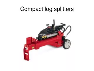
Compact log splitters
Compact log splitters. Splitting force Engine Pump Log Capacity Hydraulic Tank Capacity Cycle Time Operation Log Cradles Warranty . 8 Tons 123cc OHV Engine Single stage 7.4LPM @ 3500 RPM Up to 19“ 1.5 Gallons 24 Seconds Horizontal Included 2-Year Limited.

Compact log splitters
E N D
Presentation Transcript
Splitting force Engine Pump Log Capacity Hydraulic Tank Capacity Cycle Time Operation Log Cradles Warranty 8 Tons 123cc OHV Engine Single stage 7.4LPM @ 3500 RPM Up to 19“ 1.5 Gallons 24 Seconds Horizontal Included 2-Year Limited Specifications
Using the Log splitter • Remove the locking pin. • Slide the cylinder back until the trunnions rest in their cradle, pressing against the safety switch. • Re-install the locking pin in its hole. Locking pin Cylinder extended to the operating position
NOTE: the engine will not run unless the safety switch is depressed. Locking pin cradle Trunnion Safety switch Trunnions pushing in the safety switch
Storing the log splitter • For storage, run it out of fuel. • Retract the cylinder over the beam. • The unit can be stored in the vertical or horizontal position.
Pump • Please note that the pump is rated in LPM (Liters Per Minute). • The flow rate of this pump 2 GPM, this volume is so low that a 10% change in flow would still be about 2 GPM. • Therefore it is recommended that all flow tests be done using LPM as a measurement scale.
Valve • This log splitter uses the same valve assembly as the bigger MTD log splitters. Valve assembly Grab handle
Oil Change • To change the oil, remove the drain plug. NOTE: Replace the aluminum gasket before installing the drain plug. Aluminum gasket Drain plug
Air filter • Access the air filter by removing the thumb screw and opening the filter cover. • This engine has a foam pre-cleaner and a paper air filter like the rest of he MTD engines. Cover Thumb screw
Adding hydraulic fluid Vent Oil fill plug Use a SAE 10 AW oil or Dextron III (About 1.75 gal) Cycle the cylinder 12 times to bleed the system
Changing the belt • First, remove the bottom cover. NOTE: the log splitter will stand on end for easy access to the belt. • Slip the belt off of the spring loaded idler. Idlerspring Spring loaded idler
Testing the hydraulics Before testing the hydraulics: • Make sure reservoir is full with the proper fluid • The beam is oiled • Check the air filter and oil of the engine • Using a tach, set the engine to 3500 rpm • Check the belt condition and tension
Equipment needed Extra length of hose Flow gauge Various adapters
Install the flow gauge at the pump • Install the flow gauge between the pump and the inlet port of the control valve
Testing the pump • Run the log splitter until the fluid is warm. • Cycle the log splitter a dozen times to bleed the air out of the fluid.
Read the flow gauge LPM GPM Using the LPM side of the flow gauge will give a more accurate reading. It should read at least 7lpm. Start test with snubber valve open.
Testing the pump • Slowly close the snubber valve while watching gauges. NOTE: the relief valve is in the main valve assembly. When closing the snubber valve do not build pressure above 3200psi to prevent damage to the pump. • Pressure should increase, while flow stays the same. NOTE: this is a single stage pump without a bypass. Flow gauge Pressure gauge
Interpreting the results • The flow should remain constant (within 1lpm) @ 3500 rpm, regardless of pressure. • If flow drops, but engine rpm remains constant, the pump is bad. • If pressure does not build, check for a slipping belt, pulley or dropping engine rpm.
Testing the valve assembly • Install the flow gauge between the valve assembly and the return port of the cylinder. Flow NOTE: The extend port of the control valve is mounted to a nipple on the cylinder. Testing of the extend port would require removal of the valve.
Testing the valve • Extend and retract the cylinder. • Note the reading of the flow gauge while the cylinder is retracting. • Build pressure in the valve by slowly closing the snubber valve while watching the flow gauge. • Close the snubber valve completely to check the relief valve operation.
Interpreting the results • If the flow drops when pressure builds, the valve is leaking internally. • If the flow remains constant, and pressure can be built up, then the cylinder is leaking internally. • If the pump and cylinder test normal the problem is probably in the control valve. • If the relief valve is releasing below 1700psi, the valve assembly should be replaced.