Download

1 / 38
390 likes | 414 Vues
Learn about creating class diagrams, attributes, operations, visibility, relationships, and more in system analysis and design using UML.

E N D
Part V: Software Engineering and Implementation Lecture Note 16Unified Modeling Language (UML) Class Diagram and Statechart Diagram Systems Analysis and Design Kendall & Kendall Sixth Edition CS206 System Analysis & Design Note 16 By ChangYu
Major Topics • Class Diagram • Class Diagram Syntax • The steps for creating a Class Diagram • Statechart Diagram • Statechart Diagram Syntax • The steps for creating a Statechart Diagram CS206 System Analysis & Design Note 16 By ChangYu
Class Diagram • Class Diagram is a static model which shows the classes and the relationships among classes that remain constant in the system over time. • It is similar to Entity-Relationship Diagram (ER), but the class diagram describes classes which include attributes and operations. • The class diagram is defined for one single use case just like the sequence diagram was defined for a single use case. CS206 System Analysis & Design Note 16 By ChangYu
Example An example illustrates a class diagram reflecting the classes and relationships for the “Manage Appointment” use case.
Syntax Class 1 • attribute 1 • +operation1()
Class • Class stores and manages information in the system. • During analysis: classes can refer to the people, place, events, and anything about the system. • During design and implementation – specific artefacts, such as windows, forms, and other objects used to build the system. • Each class has three compartment. Class’s name (top), Attributes (middle), Methods (bottom) CS206 System Analysis & Design Note 16 By ChangYu
Attribute • Attribute are properties of the class about which we want to capture information. • Example: Person class contains the attributes last name, first name, address, phone, and birth date. • At times, you may want to store derived attributes, which are attributes that can be calculated or derived. These special attributes are denoted by placing a slash ( / ) before the attribute’s name which can be derived by subtracting the patient’s birthday from the current date. • Example: person class contains a derived attributes called “/age”. CS206 System Analysis & Design Note 16 By ChangYu
It is also possible to show the visibility(能見度) of the attribute on the diagram. Visibility relates to the level of information hiding to be enforced for the attribute. • The visibility of an attribute can be • Public(+) : is one that is not hidden from any other object. Other objects can modify its value. • Protected (#) : is one that is hidden from all other classes except its immediate (最接近的) subclasses. • Private (-) : is one that is hidden from all other classes. • The default visibility for an attribute is normally private. CS206 System Analysis & Design Note 16 By ChangYu
Operations • Operations are functions that a class can perform. • The functions are available to all classes are not explicitly shown within the class rectangle. • Example: create new instance, return a value for a particular attribute, set a value for a particular attribute or delete a instance. • Operations that are unique to the class are included in the class rectangle. • Example: “generate cancellation fee” in the Bill class. “cancel without notice” in the Appointment class.
The three kinds of operation: • Constructor operation: to create a new instance of a class. • Example, “insert()” in the patient class that creates a new patient instance as patients are entered into the system. • This kind operations are not shown on class diagram, because they are available to all the class. 2. Query operation: determines the state of an object and makes information about the state available to the system, but it will not alter the object. • Example, the calculate_last_visit() that determines when a patient last visited the doctor’s office will result in the object’s being accessed by the system, but it will not result in any change to its information.
3.An update operation will change the value of some or all of the object’s attributes, which may result in a change in the object’s state. • Example: a change_status() operation changes the status of a patient from new to current, or schedule_appointment(appointment) operation associates a patient with a particular appointment. CS206 System Analysis & Design Note 16 By ChangYu
Relationship • A primary purpose of the class diagram is to show the relationships or associations, that classes have with one other. • These are depicted on the class diagram by drawing lines between class. Similar to the relationships on the ER diagram. • An association has a name, participating class and multiplicity. • When multiple classes share a relationship, a line is drawn and labeled with either the name of the relationship or the roles that the classes play in the relationship. CS206 System Analysis & Design Note 16 By ChangYu
Example: • The class Patient and the class Appointment are associated with one another whenever a patient schedules an appointment. • Thus a line labeled “schedules” connects patient and appointment, representing exactly how the two classes are related to each other. • Also notice that there is a small solid triangle beside the name of the relationship. The triangle allows a direction to be associated with the name of the relationship. CS206 System Analysis & Design Note 16 By ChangYu
A Class Shares a Relationship with Itself Example: • A patient’s being the primary insurance carrier for other patients (e.g. their spouse, children) • A line named primary insurance carrier was drawn between the patient class and itself to depict the role that the class plays in the relationship . • A plus sign (+) is placed before the label to communicate that it is a role as opposed to the name of the relationship.
Relationship also have multiplicity, which documents how an instance of an object can be associated with other instances. • Numbers are placed on the association path to denote the minimum and maximum instances that can be related through the association in the format: Minimum number .. Maximum number • The numbers specify the relationship from the class at the far end of the relationship line to the end with the number. Example, there is a “0..*” on the appointment end of the “patient schedule appointment” relationship. This means that a patient can be associated with zero through many different appointments. At the patient end of this same relationship there is a “1”, meaning that an appointment must be associated with one and only one patient.
Examples of UML notations that indicate the nature of the relationship between instances of one class and instances of another class. CS206 System Analysis & Design Note 16 By ChangYu
An Association Class • It has its own attributes and operations. • It is shown as a rectangle attached by a dashed line to the association path, and the rectangle’s name matches the label of the association. • Example : An illness (e.g. the flu) can be Associated with many symptoms (e.g. sore throat, fever) and a symptoms can be associated with many illnesses. CS206 System Analysis & Design Note 16 By ChangYu
Aggregation Association • When classes actually comprise (包含) other classes. • An aggregation expresses a part-of relationship between a components object and an aggregate object. • An aggregation is a stronger form of association relationship . It is represented with a hollow diamond at the aggregate end. • An aggregation involves a set of distinct object instances, one of which contains or is composed of the others. • Example:
Aggregation Examples: Health Team Administrative Personnel Doctor Nurse Doctors, nurses, and administrative personnel are “ a part of” a health care team. A car comprise the engine, doors, and transmission.
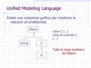
Generalization Association • In generalizing a set of object classes into a more general class, we abstract not only the common attributes and relationship, but also the common operations. • A generalization path is shown as a solid line from the subclass to the superclass, with a hollow triangle at the end of, and pointing toward, the superclass.
Example: • This figure tells us that those employees and patients are kinds of persons. • Nurses, doctors and administrative staffs are kinds of employee. • Remember that the generalization relationship occurs when you need to use words such as “is a-kind-of” to describe the relationship.
Creating a Class Diagram Step 1: Identify Classes • Identify what classes should be placing on the diagram. • A class diagram shows the classes that are needed for the system as a whole. • Note: Creating a class diagram to represent the classes and relationships only for the Customer Places Order use case. CS206 System Analysis & Design Note 16 By ChangYu
Step 2: Draw Relationships between the classes. • Example, the customer class is related to the other class because a customer “places” an order. • The customer can place zero or many orders • An order can be associate with one and only one customer.
Step 3: Examine the model for opportunities to use aggregation or generalization associations. • E.g. CD Selections decided that marketing material is best viewed as a collection of different kinds of promotional materials (e.g. artist information, sample clips and reviews), it may be best to model marketing material as an aggregation that includes other classes. • E.g. CD Selections may want to leave room for the opportunity to sell items other than CDs. Therefore, the class diagram could include a class called product that is a generalization of CD. CS206 System Analysis & Design Note 16 By ChangYu
In this figure shows the aggregation and generalization associations. Class Diagram for Customer Places Order
Statechart Diagram • A statechart diagram is a dynamic model that shows the different states of the class and what events cause the class to change from one state to another. • Typically not used for all classes, but just to help simplify the design of algorithms for methods of complex classes. • E.g. a patient can change over time, from being “new” to “current” or “former”. CS206 System Analysis & Design Note 16 By ChangYu
This example illustrates a statechart diagram representing the patient class in the context of a hospital environment. • A patient enters a hospital and is admitted(許可) after checking in. • If a doctor finds the patient to be healthy, he or she will be released and is no longer considered a patient after two weeks have elapsed (時間過去). • If a doctor finds the patient to be unhealthy, he or she remains under observation until the diagnosis has been changed.
State • A state is a set of values that describe an object at a specific point in time. • It represents a point in an object’s life in which it satisfies some condition, performs some action, or waits for something to happen. • Example (page29), states include entering, admitted, released and under observation. • A state symbol is a rectangle with rounded corners with a descriptive label that communicates a particular state. • An initial state symbol is a small solid filled circle. • The attributes or properties of an object affecting the state that it is in. • Example (page 29), attributes that influence state transitions are the patient’s hospital status and the diagnoses. CS206 System Analysis & Design Note 16 By ChangYu
Event • An event is something that takes place at a certain point in time and changes a value(s) that describe an object, which in turn changes the object’s state. • Example (page 29), checking into the hospital, a healthy diagnosis and a two-week time lapse are events that cause changes to the patient’s state. • Arrows connect the state symbols, representing the transitions between states. • Each arrow is labeled with the appropriate event name and any parameters or conditions that may apply. • A guard condition is a Boolean expression that includes attribute values, which allows a transition only of the condition is true. • Example (page 29), the two transitions from admitted to released and under observation contain guard conditions.
Creating a Statechart Diagram A statechart diagram is drawn to depict a single class from a class diagram. When the classes are very dynamic and complex, it is necessary to have a good understanding of their states over time and the events that triggers the changes. • Set the context. • Identify the initial, final and stable states of the object. • Determine the order in which the object will pass through the stable states. • Identify the events, actions and guard conditions associated with the transitions. • Validate the statechart diagram. CS206 System Analysis & Design Note 16 By ChangYu
Applying the concepts at CD Selections Step 1:Determine the context of the statechart diagram • The context of a statechart diagram is usually a class. However, it also could be a set of classes, a subsystem, or an entire system. CS206 System Analysis & Design Note 16 By ChangYu
Step 2: Identify the States • Identify the various states that an order will have over its lifetime. • This information is gain from reading the use case reports, talking with users, and relying on the requirements-gathering techniques. • Begin by writing the steps of what has happened to an object over time, from start to finish. • The following is an order from start to finish, from the order’s perspective: CS206 System Analysis & Design Note 16 By ChangYu
The customer creates an order on the web. • The customer submits the order once he or she is finished. • The credit authorization needs to be approved for the order to be accepted. • If denied, the order is returned to the customer for changes or deletion. • If accepted, the order is placed. • The order is shipped to the customer. • The customer receives the order. • The order is closed. CS206 System Analysis & Design Note 16 By ChangYu
Step 3: Determine the sequence of the states that an object will pass through during its lifetime. • Using this sequence, we can place the states on to the statechart diagram, in a left to right order. CS206 System Analysis & Design Note 16 By ChangYu
Step 4: Identify the events, actions, and guard conditions associated with the transitions (轉變) between the states of the object. • Identify unique states that the order possesses and determine exactly what causes each state to occur. • Place state figures on the diagram to represent the states and label the transitions to describe the events that are taking place to cause the state changes. • Example, the event “order is created” move the order from the “initial” state to the “In process” state. • During the “Processing” state, a credit authorization is requested. The guard condition “Authorization =Approved” prevents the order to move from the “Processing” state to the “Placed” state unless the credit authorization has been approved. • Also, the guard condition “Authorization = Denied” prevents the order to move from the “Processing” state to the “Denied” (拒絕接受) state unless the credit authorization has been denied. CS206 System Analysis & Design Note 16 By ChangYu
Step 5: Validates the statechart by ensuring that each state is reachable and that it is possible to leave all states except for the finial states. CS206 System Analysis & Design Note 16 By ChangYu