Download
1 / 15
150 likes | 192 Vues
Explore the detailed design and functionality of the ATLAS Muon Trigger Sector Logic Board, essential for particle detection and data acquisition in high-energy physics experiments. This comprehensive guide covers the intricate architecture, operation principles, and integration with other components to enhance research accuracy and efficiency.

E N D
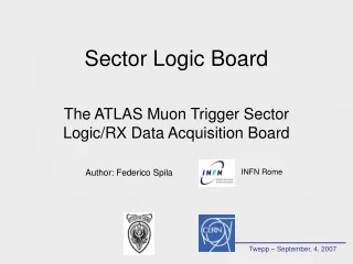
Twepp – September, 4, 2007 Sector Logic Board The ATLAS Muon Trigger Sector Logic/RX Data Acquisition Board Author: Federico Spila INFN Rome
SIDE C 3 Planes of RPC Detectors Outer HV side Middle-pivot SIDE A Inner 3 Planes of RPC Each with 6 or 7 Chambers RO Side Trigger Tower Twepp – September, 4, 2007 1/13 LVL1 Muon Barrel Trigger 16 Sectors on the Azimuthal Plane 32 Geometrical Sectors 6 or 7 Trigger Towers on each Trigger Sector 64 Trigger Sectors
Low Pt PAD BOX • Read Read-Out Data • Implement Event Building • Send Output Data to ROD High Pt PAD BOX To Sector Logic… …From PAD • Read Trigger Data • Implement Trigger algorithm • Send Output Data to MUCTPI Twepp – September, 4, 2007 2/13 Lvl1 Trigger Electronics ON Detector Electronics Off Detector Electronics
MUCTPI-Interface Sector Logic Read-Out Data: Backplane Connection VME CRATE VME CRATE Central Trigger Processor MUCTPI - Interface Sector Logic ROD Optical receivers MUCTPI SCSI Connectors Trigger Data are LVDS Parallel Bus Trigger Data L1 Barrel Trigger L1 End-Cap Trigger External cables -> LVDS BUS …To MUCTPI board Twepp – September, 4, 2007 3/13 VME Crates USA 15 Room 16 VME Crates Each takes data from 2 Geometrical Sectors Each takes data from 2 Trigger Sectors In Total 64 Sector Logic Boards
ROD ROD ROD ROD Sector Logic Sector Logic Sector Logic Sector Logic Sector Logic Sector Logic Sector Logic MUCTPI - Interface MUCTPI - Interface MUCTPI - Interface MUCTPI - Interface MUCTPI - Interface MUCTPI - Interface MUCTPI - Interface Twepp – September, 4, 2007 4/13 ROD-BUS • SL <-> ROD • Sends Read-Out Data • Receives TTC Signals Real ROD Block VME Crate ROD Block 32 ROD Modules as the ATLAS Geometrical Sectors • MUCTPI-Interface • Sector Logic • ROD • Sector Logic • MUCTPI-Interface ROD BUS mounted on a VME Back-Panel Each ROD reads 2 Sector Logics • SL <-> MUCTPI-Interface • Sends Trigger Data • Receives Service Signals
Xilinx Virtex2 XC2V 1000 Xilinx Virtex2 XC2V 2000 Serializer chip Twepp – September, 4, 2007 5/13 Sector Logic Schema 4 G2Link RX Cards VME Communication JTAG Other Services All Sector Logic features 40 bit TTL input -> 8 bit LVDS output stream Speedrate 240 Mbyte/s Each with 2 Optical link receivers VME FPGA SL FPGA
VME FPGA VME64x Client Protocol 8 Registers 1 FIFO SBC (VME Server) SL FPGA 44 Registers 12 FIFOs Twepp – September, 4, 2007 6/13 VME FPGA Firmware VME BUS Custom Master-Slave Protocol All Registers & FIFOs 32 bit lenght 7 bit Address
24 bit bidirectional VME SL 16 bit Data 7 bit Address 1 bit R/W Twepp – September, 4, 2007 7/13 Master-Slave Protocol External FIFO Access Configuration signals of Link Cards & Serializer JTAG signals VME FPGA is the Master Transmit first the low significant 2 bytes, after the more significant 2 bytes
Twepp – September, 4, 2007 8/13 SL FPGA Firmware SL FPGA Link 0-1 …To VME FPGA CLOCK DISTRIBUTION TRIGGER LOGIC READ-OUT LOGIC VME ACCESS Link 2-3 …To Serializer Link 4-5 …To MUCTPI-I Link 6-7
When a MUON candidate is detected The Sector Logic receives Trigger data From 1 or more PADs Link 0-1 TRIGGER LOGIC Link 2-3 Link 4-5 …To MUCTPI-I Link 6-7 Twepp – September, 4, 2007 9/13 Trigger Logic BC 1: Solves the PAD Overlap • 32 Trigger output word • Information about the2 Muon Candidates • BC-ID • FLAG “More than 2 candidates” • 16 bit Trigger Word • BC-ID • Overlap • Threshold • ROI BC 2: Detects the first High Pt muon using a 8x7 Matrix comparator BC 3: Detects the second High Pt muon using a 8x6 Matrix comparator Total processing Time: 5 BC (125 ns) Store Trigger Data in an internal FIFO Used by the Read-Out Logic
16 bit Pad Frame Fifo 3 Fifo 6 Fifo 5 Fifo 4 Fifo 2 Fifo 1 Fifo 0 PAD Header Link 0-1 Data… Data Produces the Output Packet READ-OUT LOGIC 32 bit SL Frame SL Header PAD Footer Link 2-3 Pad 0 Frame Pad 1 Frame Pad 2 Frame Pad 3 Frame Pad 4 Frame Pad 5 Frame Pad 6 Frame Trigger Frame …To Serializer Event Building Link 4-5 VME FIFO Check Link 6-7 SL Footer FIFO OUT Serializer Fifo Trig Twepp – September, 4, 2007 10/13 Read-Out Logic When a L1A Signal arrives from TTC The Sector Logic receives Read-Out data From all the PADs L1-ID & BC-ID are syncronized 80 MHz Clk
…To VME FPGA VME ACCESS Twepp – September, 4, 2007 11/13 VME SL Logic • GENERAL PURPOSE BOARD for Testing • PADs • Sector Logics • RODs • MUCTPIs Master-Slave Custom Protocol • - Write input FIFOs simulating PADs • - Write Timing signals simulating the TTC • - Write the Output Data directly to ROD • Write the Output Data directly to MUCTPI • Mounting G2Link TX, we can emulate the PAD
TTC Clock Input FIFO Clk Serializer Clk FIFO 2 FIFO 0 FIFO 4 FIFO 5 FIFO 6 Link 1 FIFO 3 Link 2 Link 3 Link 4 Link 6 Link 0 FIFO 1 Link 5 FIFO OUT Event Building Clk Twepp – September, 4, 2007 12/13 Timing Logic VME Clock LOCAL Clock VME ACCESS VME TRIGGER READ-OUT SERDES MUCTPI
VME VME SBC SBC MUCTPI-I MUCTPI-I MUCTPI-I MUCTPI-I ROD ROD Sector 5 Side A Sector 5 Side C SL SL SL SL Twepp – September, 4, 2007 13/13 Conclusions & M4 RUN DAQ Software See Cosmic Muon events in Read-Out Data All The L1-ID & BC-ID of the 2 Sectors are syncronized M4 Integrated Cosmic Run Future: we will test and install all the other 60 SL boards L1 Trigger CALO L1 Trigger End-Cap MUCTPI Central Trigger Processor
Twepp – September, 4, 2007 THE END