Network Software: The Protocol Hierarchy
Network Software: The Protocol Hierarchy. In realty, no data is transferred from layer n on any two machines. Data and control information is passed to the layer below.

Network Software: The Protocol Hierarchy
E N D
Presentation Transcript
Network Software: The Protocol Hierarchy • In realty, no data is transferred from layer n on any two machines. Data and control information is passed to the layer below. • Additional information including protocol control information may be appended by each layer to data as it travels from higher to lower layers in the form of layer headers. • Below layer 1 is the physical medium where the actual communication occur over communication channels (copper wires, optical fibers, wireless channel etc.) • Between adjacent layers an interface defines which primitive operations and services the lower layer offers to the upper layer. • The set of layers and associated protocols is called a network architecture.
An Example of Information Flow In Layer 5 M = Message H = Header
Layer headers are appended by each network layer to the original user data as it travels from higher to lower layers. Nested Layer Protocol Headers
The OSI Reference Model OSI = Open Systems Interconnection, 1983 The layers of The OSI Reference Model were never fully adopted by a real network architecture.
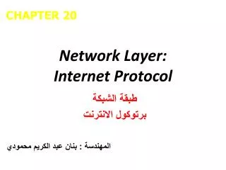
OSI Reference Model Layers • The Physical Layer: • Concerned with transmitting raw bits over a communication channel (bit timing, voltage ..) • The Data Link Layer: • Transform raw transmissions into error-free data. • Data grouped in frames with error detection and/or correction bits added. • Frames are sent and acknowledged by this layer. • The Network Layer: • Controls the operation of the subnet. • Concerned with routing of data packets from source to destination. • Handles protocol incompatibilities between different networks.
OSI Reference Model Layers • The Transport Layer: • Accepts data from the session layer and may split it into smaller units. • Ensures that message units arrive correctly at the destination. • Determines what type of service is provided to the session layer. • The Session Layer: • Allows users on different machines to establish sessions (login, file transfer, etc.) • The Presentation Layer: • Concerned with syntax and semantics of the information transmitted. • The Application Layer: • Handles common needed high level network protocols (e.g. email, FTP, HTTP, TELNET, etc.)
Data Transmission in The OSI Model Some headers may be empty
Data Transmission Channel Characteristics • Channel Noise: A small amount of background interference or stray energy present on the channel (usually electro-magnetic)that carries no data or information. • Main cause of transmission errors. • Given as the signal to noise ratio S/N and measured in decibels (dB). • Channel Bandwidth: The size of the range of frequencies that can be transmitted through a channel. Measured in Hertz (Hz). Affected by: • Type and physical characteristics of media used. • Amount of noise present in transmission channel • Data encoding method used. • Channel Data Transmission Rate (or Bit Rate): The maximum number of bits that can be transmitted per unit time through the physical medium. Measured in bits per second (bps). • Channel Utilization: The fraction of the channel’s data rate actually used to transmit data.
Data Transmission Channel Characteristics • Channel Latency, or Propagation Delay: The amount of time needed for information to propagate from source to destination through the channel. It is the distance divided by the signal propagation speed (usually the speed of light). Depends on: • Media characteristics • Signal propagation speed • Transmission distance • Transmission Delay: The time it takes to transmit a message through the channel. It is the size of the message in bits divided by the data rate (in bps) of the channel over which the transmission takes place. • Bit Length: The length of a one-bit signal being transmitted = signal propagation speed / data transmission rate Example: Channel data-rate is 10Mbps. One bit is transmitted in 10-7 seconds. Since signals propagate in a medium at about 200,000 km/s, ie 2*108 m/s, bit-length is: 10-7 * 2 * 108 = 20 meters.
The Physical Layer: Basic Information Encoding Theory • Any well behaved periodic function g(t) with a period T= 1/f can be decomposed into a summation of a series of sine and cosine terms (Fourier Series): • Any physical transmission channel can transmit frequencies undiminished from 0 to some frequency fc • e.g. voice grade phone lines have a cutoff frequency of fc= 3000hz • Channel baud rate = number of changes/sec • Channel bit rate = (baud rate x number of bits/change) bits/sec
The Maximum Data Rate of A Channel: Nyquist’s Theorem • The maximum data rate of a finite bandwidth noiseless transmission channel with bandwidth H is given by Nyquist’s theorem : Maximum data rate = 2 H log2 V bits/sec where V is the number of discrete levels. • For binary transmission: Maximum data rate = 2 H log 2 2 = 2 H • Given a channel with bandwidth H Hz, a signal S to noise N ratio of (10 log10 S/N) dB(decibels) , the maximum data rate of the channel (or channel bandwidth) is given by Shannon as: Maximum number of bits/sec = H log2 (1 + S/N) • e.g. phone lines have S/N ratio of 30 dB and H = 3000, according to Shannon: 30 dB = 10 log10 S/N Signal to noise ratio = S/N = 10 30/10 = 103 = 1000 Maximum transmission rate = 3000 log2 (1 + 1000) » 30000 bps
Data Multiplexing • Transmission links (channels) present in a single network usually have a wide range of available bandwidths. • To maximize the utilization of higher bandwidth links: • Data from several lower-bandwidth transmission links is usually multiplexed onto a single high-bandwidth link. • Several data multiplexing methods are used: • Frequency Division Multiplexing (FDM) • Used in voice channels • Uses analog circuits • Wavelength Division Multiplexing (WDM): • Used in fiber optic transmission lines. • Time Division Multiplexing (TDM): • Several digital channels are combined from local subnets.
Time Division Multiplexing (TDM) • Digital data from a number of low-bandwidth channels is combined into a single high-bandwidth channel. • Data from different channels is multiplexed over time to occupy alternating time slots. • Example: T1 digital channels (1.554 Mbps) usually combine data from 24, 56000 bps channels.
Virtual Circuits • When a virtual circuit is established: • The route is chosen from beginning to end (circuit setup needed) • Routers or switches along the circuit create table entries used to route data transmitted on the virtual circuit. • Permanent virtual circuits - Switched virtual circuits
Virtual Communication Actual Communication Data Link Layer: Virtual Vs. Actual Communication Frames
Data Link Layer: Framing • The character count method: • The frame header includes the count of characters in the frame • A transmission error can cause an incorrect count causing the source and destination to get out of synchronization • Rarely used in actual data link protocols A character stream with no errors A character stream with one error
Network Layer Data at the sender Data after character stuffing by the Data Link Layer at the sender Network Layer Data at the Receiver Data Link Layer: Framing Using Starting and ending characters, with character stuffing • Each frame starts with the ASCII character sequence DLE (Data Link Escape) and STX (Start of TeXt) and ends with DLE ETX (End of TeXt) • When binary data is transmitted where (DLE STX or DLE ETX) can occur in data, character stuffing is used (additional DLE is inserted in the data). • Limited to 8-bit characters and ASCII.
Data Link Layer: Framing • Bit-Oriented Using Start/End Flags: • Each frame begins and ends with 01111110 • Bit stuffing: After each five consecutive ones in a data a zero is stuffed • Stuffed zero bits are removed by the data link layer at receiving end. The Original Data Data appearing on the line after bit stuffing Data received after destuffing
Data Link Layer: Error Detection/Correction • Simplest error detection : Parity bits and checksum (sum of 1’s in data). • Error-detecting and -correcting codes: • m data bits + r redundant bits added • n = m + r transmitted in frame. • Only 2m code words out of possible 2m+r words are legal. • The Hamming distance --minimum number of positions any two legal code words differ-- of a code defines its error detection/correction ability. • To detect d errors code Hamming distance = d + 1 • To correct d errors code Hamming distance = 2d + 1 • Some codes are more suitable to correct burst errors rather than isolated errors. • Polynomial codes (Cyclic Redundancy Codes or CRC) are characterized by a generating polynomial G(X)
Calculation of Polynomial Code (CRC) Checksum 1. For degree of generating polynomial G(x) = r , append r zero bits to low-order of frame. The frame now has m+r bits. 2. Divide the bit string corresponding to G(X) into the bit string xrM(x) mod(2) 3. Subtract the remainder from the bit string xrM(x) mod(2) Frame: 1 1 0 1 0 1 1 0 1 1 Generator: 1 0 0 1 1 G(X) = X4 + X + 1 Message after appending four 0’s: 1 1 0 1 0 1 1 0 1 1 0 0 0 0 Transmitted Frame: 1 1 0 1 0 1 1 0 1 1 1 1 1 0
Hardware Computation of CRC For G(x) = x16 + x12 + x5 + 1 An Example Frame Format with CRC bits
Data Link Layer: Flow ControlStop-and-Wait Data Link Protocols • Such elementary protocols are also called PAR (Positive Acknowledgment with Retransmission) or ARQ (Automatic Repeat reQuest). • Data frames are transmitted in one direction (simplex protocols ) where each frame is individually acknowledge by the receiver by a separate acknowledgment frame. • The sender transmits one frame, starts a timer and waits for an acknowledgment frame from the receiver before sending further frames. • A time-out period is used where frames not acknowledged by the receiver are retransmitted automatically by the sender. • Frames received damaged by the receiver are not acknowledged and are retransmitted by the sender when the expected acknowledgment is not received and timed out. • A one bit sequence number (0 or 1) is used to distinguish between original data frames and duplicate retransmitted frames to be discarded . • Such protocols result in a substantial percentage of wasted bandwidth and may fail under early time-out situations.
Data Frame 4 Data Frame 5 Data Frame 6 Data Frame 1 Data Frame 2 Data Frame 3 Frame transmission time = (d+h)/b b = channel bandwidth One way Channel delay or latency l Sender Receiver : : : : : : Protocol 1: An Unrestricted Simplex Protocol • Transmission in one direction • The receiver is always ready to receive the next frame (has infinite buffer storage). • Error-free communication channel. • No acknowledgments or retransmissions used. • If frame has d data bits and h overhead bits, channel bandwidth b bits/second: maximum channel utilization = data size/frame size = d/(d + h) maximum data throughput = d/ (d + h ) * channel bandwidth = d/ (d + h ) * b
Data Frame 1 Data Frame 2 Time Protocol #2: A Simplex Stop-and-Wait Protocol • Simplex: Data transmission in one direction • The receiver may not be always ready to receive the next frame (finite buffer storage). • Receiver sends a positive acknowledgment frame to sender to transmit the next data frame. • Error-free communication channel assumed. No retransmissions used. • Maximum channel utilization » (time to transmit frame /round trip time) * d/(d + h) »d/ (b * R) • Maximum data throughput » channel utilization * channel bandwidth »d/ (b * R) * b = d/ R Round trip time, R Acknowledgment Frame Sender Receiver Acknowledgment Frame : : : : : :
Round trip time, R Data Frame 1, sequence # 0 Ack Frame, sequence # 0 Time Data Frame 1, sequence # 1 Receiver Sender Ack Frame, sequence # 1 Data Frame 1, sequence # 0 Protocol 3: A Simplex Positive Acknowledgment with Retransmission (PAR) Protocol • The receiver may not be always ready to receive the next frame (finite buffer storage). • Noisy communication channel; frames may be damaged or lost. • Frame not received correctly with probability p • Receiver sends a positive acknowledgment frame to sender to transmit the next data frame. Any frame has a sequence number, either 0 or 1 • Maximum utilization and throughput similar to protocol 2 when the effect of errors is ignored.
Data Frame 1, sequence # 0 Error: Frame lost or damaged, with probability p Time Ack Frame, sequence # 0 Protocol 3: A Simplex PAR Protocol (continued)Effect of Errors • The sender starts a timer when transmitting a data frame. • If data frame is lost or damaged (probability = p): • Receiver does not send an acknowledgment • Sender times out and retransmits the data frame Start timer X Time-out Interval Time-out Retransmit frame Receiver Data Frame 1, sequence # 0 Sender
Data Link Layer: Flow Control Sliding Window Protocols • These protocols allow both link nodes (A, B) to send and receive data and acknowledgments simultaneously. • Acknowledgments are piggybacked into an acknowledgment field in the data frame header not as separate frames. • If no new data frames are ready for transmission in a specified time, a separate acknowledgment frame is generated to avoid time-out. • Each outbound frame contains a sequence number ranging from 0 to 2 n-1 (n-bit field). N = 1 for stop-and-wait sliding window protocols. • Sending window: A set of sequence numbers maintained by the sender and correspond to frame sequence numbers of frames sent out but not acknowledged. • The maximum allowed size of the sending window w correspond to the maximum number of frames the sender can transmit before receiving any acknowledgment without blocking (pipelining). • All frames in the sending window may be lost or damaged and thus must be kept in memory or buffers until they are acknowledged.
Sliding Window Data Link Protocols • Receiving window:A set of sequence numbers maintained by the receiver and indicate the frames sequence numbers it is allowed to receive and acknowledge. • The size of the receiving window is fixed at a specified initial size. • Any frame received with a sequence number outside the receiving window is discarded. • The sending window and receiving window may not have the same upper or lower limits or have the same size. • When pipelining is used, an error in a frame is dealt with in one of two ways: • Go back n: (Example: Protocol 5) • The receiver discards all subsequent frames and sends no acknowledgments. • The sender times out and resends all the discarded frames starting with faulty frame. • Selective repeat: (Example: Protocol 6) • The receiving data link stores all good frames received after a bad frame. • Only the bad frame is retransmitted upon time-out by the sender.
A Sliding Window Protocol of Size 1 with a 3-bit Sequence Number (b) After the first frame has been sent (c) After the first frame has been received (d) After the first acknowledgment frame has been received (a) Initial state
DF 1, seq # 0 Data Frame 1, seq # 0 Data Frame 2, seq # 1 DF 2, seq # 1 DF 3, seq # 2 Ack Frame, seq # 0 DF 4, seq # 3 ACK F, seq # 0 Ack Frame, seq # 1 Data Frame 3, seq # 0 Time Ack Frame, seq # 0 Data Frame 4, seq # 1 Ack Frame, seq # 1 Difference Between PAR and Sliding Window Protocols Positive Acknowledgment with Retransmission Shown Here: Four Data Frames Transmitted Sliding Window sequence # from 0 to 3 Stop-and-Wait Round Trip Time, R Ack F, seq # 1 Ack Frame, seq # 2 Ack Frame, seq # 3 : : : : : : : : : : : : Sender Receiver Sender Receiver
After two frames have been acknowledged After nine frames have been acknowledged A 4-Frame Sending Window Initial window Unacknowledged or Pending Frames
Channel Utilization & Data Throughput For Sliding Window Protocols b = Channel bandwidth or transmission rate bits/sec FS = Frame size = # of data bits + # overhead bits = d + h R = Channel round trip time N = Send/receive window size p = Probability frame a data frame is lost or damaged • Ignoring errors, condition to maximize Utilization/Throughput: Time to transmit N frames ³ Round trip time FS/b * N = (d + h)/b * N ³ R Under this condition: Maximum channel utilization » data size/frame size = d/(d + h) Maximum data throughput »d/FS = d/(d + h ) * b • Including the effect of errors only on data frame; assuming selective repeat: On the average p data frames have to be retransmitted Under these condition: Total Data Frame overhead = h + p * FS Maximum channel utilization »d/[(1 + p)*FS] Maximum data throughput »d/[(1 + p)*FS] * b
Effect of Errors in Sliding Window Protocols (a) Effect of an error when the receiver size is 1 (b) Effect of an error when the receiver size is large
State Transition Diagram For Protocol 3 • The protocol state machine states are represented by XYZ • X = 0 or 1 depending on the sequence number of the frame the sender is attempting to send. • Y = 0 or 1 depending on the sequence number of the frame the receiver expects. • Z = 0, 1, A or empty (-) corresponding to the state (content) of the channel.
Data Link Protocol Example: HDLC - High-Level Data Link Control • Bit-oriented protocol derived from IBM’s SNA data link protocol SDLC (Synchronous Data Link Control). • Frame Types: Information, Supervisory, Unnumbered. • Uses sliding window with 3-bit sequence numbers. • Uses CRC-CCITT for error control. • Protocol commands include: • DISC (DISConnect) used to disconnect a machine from the line. • SNRM (Set Normal Response Mode) brings a machine online and sets one machine as channel master and the other as slave ( was used for dumb terminals when connected to mainframes). • SABM (Set Asynchronous Balanced Mode). • FRMR (FRaMe Reject) rejects a frame with correct checksum with impossible structure.
HDLC Bit-Oriented Frame Format Information Frame Frame Sequence # Poll/Final Next Frame Expected Supervisory Frame Unnumbered Frame
Internet Data Link Protocols: Serial Line IP (SLIP) RFC 1055 • Send raw IP packets with a flag byte (0xC0) at the end for framing with character stuffing (data 0xC0 replaced with 0xDB 0xDC). • Recent versions use header compression by omitting header fields in consecutive packets and frames. • Does not include any form of error detection or correction. • Supports only one network protocol: IP (Internet Protocol). • Dynamic IP address assignment not supported. • Lacks any form of authentication.
Internet Data Link Protocols: Point-to-Point Protocol (PPP) • Uses standard HDLC framing byte (01111110) with error detection. • Uses Link Control Protocol (LCP) for brining lines up, option negotiation, and to bring lines down. • Network layer options and configurations are negotiated independent of the network layer used by utilizing different NCPs (Network Control Protocol) packets for each supported network layer. • Support for several packet types by using a protocol field: • Network protocols (protocol field starts with 0): IP, IPX, AppleTalk etc. • Negotiating protocols (protocol field starts with 1): LCP, NCP. • PPP is used for both dial-up network access and for router-to-router communication in subnets.
PPP Frame Format & Transition Diagram PPP Frame Format for unnumbered mode operation. Simplified PPP phase diagram for brining a line up or down.
Data Link In Broadcast Networks: The Media Access Sublayer • Broadcast networks with multi-access (or random access) shared channels include the majority of LANS, all wireless and satellite networks. • Medium Access Control (MAC): Protocols to allocate a single shared broadcast channel among competing senders by determining which sender gets access to the channel next and transmit its data. • Static Channel Allocation: Frequency Division Multiplexing (FDM), Time Division Multiplexing (TDM) --- too wasteful of available bandwidth. • Dynamic Channel Allocation: No predetermined sender access order to the channel.
Dynamic Channel Allocation: Protocol Assumptions • N independent stations (senders or, computers etc.) • A station is blocked until its generated frame is transmitted. • Probability of a frame being generated in a period of length Dt is lDt where l is the arrival rate of frames. • Only a single channel is available • The transmission of two or more frames on the channel at the same time creates a collision and destroyed data. • Time can be either: Continuous or slotted. • Carrier sense: A station can sense if a channel is busy before transmission. • No Carrier sense: Timeout used to sense loss of data.
Multiple Access Protocols: Pure ALOHA • Stations transmit whenever data is available at arbitrary times (forming a contention system). • Colliding frames are destroyed • Frame destruction sensed by listening to channel: • Immediate collision feedback in LANs • 270 msec feedback delay in satellite transmission. • When a frame is destroyed the sender waits a random period of time before retransmitting the frame } Users Single channel Collision
Frame Throughput of Pure ALOHA • Infinite sender population assumed. • New frames rate (or frames success rate): Poisson distribution with mean rate S frames/frame time. • Combined frame rate with retransmissions : G frames/frame time. • S = GP0 where P0 = probability a frame is successful • t = time required to transmit a frame • A frame is successful if no other frames are transmitted in the vulnerable period from t0 to t0 + 2t • Probability k frames are generated during a frame time: • Probability of zero frames in two frame periods is P0 = e-2G • S = G P0 = G e-2G Max (S) = 1/2e at G = .5
Vulnerable period for shaded frame Time Vulnerable Period in Pure ALOHA For successful frame transmission: No other frame should be on the channel for vulnerable period equal to twice the time to transmit one frame = 2t
Slotted ALOHA • Time is divided into discrete frame time slots. • A station is required to wait for the beginning of the next slot to transmit • Vulnerable period is halved as opposed to pure ALOHA. • S = G P0 = G e-GMax (s) = 1/e at G = 1 • Expected number of retransmissions: E = eG
Carrier Sense Multiple Access (CSMA) Protocols • Medium Access Control (MAC) Protocols for shared channels where a station listens to the channel and has the ability sense the carrier and thus can detect if the channel is idle before transmitting, and possibly detect the occurrence of a collision after attempting to transmit a frame. • 1-persistent CSMA: • A ready station first listens to the channel for other transmissions. • Once it detects an idle channel it transmits a frame immediately. • In case of a collision, the stations involved in the collision wait a random period of time before retransmission. • nonpersistent CSMA: • If a ready station senses an idle channel it starts transmission immediately. • If a busy channel is sensed a station waits a random period of time before sensing the channel again. • p-persistent CSMA (applies to slotted channels): • If A ready station senses an idle channel, it transmits with probability p or defers transmission to the next time slot with probability q = 1 - p • If the next slot is idle it transmits or defers again with probabilities p, q • The process continues until the frame has been transmitted or another station has seized the channel.