Download
1 / 32
320 likes | 403 Vues
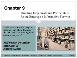
Explore tools for analyzing and documenting existing and new information systems, from context diagrams to data flow diagrams and entity-relationship modeling, with a focus on logical and physical system modeling.

E N D
CHAPTER 9 (part b) BASIC INFORMATION SYSTEMS CONCEPTS
Page 366 Figure 9.10 Physical Model of a System
Tools for the As-Is Model • Must identify existing processes, external participants, other databases or applications, and inputs and outputs • Tools used: • Procedures, policies, manuals, forms, reports • Other documentation • Group interviews Page 366
Tools for the As-Is Model Context diagram – positions the system as a whole with regard to other entities and activities with which it interacts Work process flow diagram – identifies the existing information sources, information sources that are updated, order in which steps occur, and some of the dependencies Page 367
Tools for the As-Is Model Figure 9.11 Context Diagram for Accounts Payable Page 367
Figure 9.12 Work Process Flow Diagram for Accounts Payable Page 368
Tools for the Logical To-Be Model • High-level model of a nonexistent new system • Identifies processes and data • Does not identify who does activity, where accomplished, or type of hardware or software • Describes “what” rather than “how” • Most closely associated with data flow diagrams (DFDs) Page 367
Tools for the Logical To-Be Model Figure 9.13(A) Top-Level DFD for Accounts Payable System Page 369
External Entity Data Flow Processes Data Store Figure 9.13(A) Top-Level DFD for Accounts Payable System Page 369
Tools for the Logical To-Be Model • Process of creating a DFD: • Identify entities that supply or use system information • Distinguish processes from data they use or produce • Explicate business rules that affect transformation of data to information • Identify logical relationships • Pinpoint duplicate storage and movement of data Page 369
Note process numbering scheme Figure 9.13(B) Second-Level DFD for Accounts Payable System Page 370
Tools for the Logical To-Be Model • More logical modeling required after DFDs • Need to define system’s data elements and relationships: • Data dictionary/directory (DD/D) used to define data elements • Entity-relationship diagram (ERD) used to define relationships between entities Page 371-372
Page 371 Figure 9.14 Data Dictionary Sample Entry
Tools for the Logical To-Be Model Figure 9.15 Entity-Relationship Diagram for Invoice and PO Page 372
Relational Database Terminology Figure 9.16 Key Terms for Logical Data Modeling Page 372
Tools for Documenting the Physical To-Be System • Tools for physical design represent how: • processes and data stores partitioned • program control handled • database organized • Tools include: • Program structure chart • Database design • System interface layouts Page 372-373
Program Structure Chart Page 373 Figure 9.17 Program Structure Chart
Database Design (data relationships) (Screen shot reprinted with permission from Microsoft Corporation) Figure 9.18 Relationships for Data Elements in Accounts Payable Page 374
System Interface Input Layout Form (Screen shot reprinted with permission from Microsoft Corporation) Figure 9.19 Input Form Layout for Vendor Invoice Page 375
Output Report Layout Figure 9.20 Check Register Report Layout with Sample Data Page 375
PROCESSES AND TECHNIQUES TO DELIVER INFORMATION SYSTEMS Object-Oriented Techniques • Object approach well suited for client/server applications, graphical interfaces, and multimedia data • Primary advantage is ability to reuse objects programmed by others Page 374
PROCESSES AND TECHNIQUES TO DELIVER INFORMATION SYSTEMS Object-Oriented Techniques Figure 9.21 The Promise of Object-Oriented Approaches Page 376
PROCESSES AND TECHNIQUES TO DELIVER INFORMATION SYSTEMS Core Concepts • Object • Encapsulation • Inheritance Objects communicate with each other through messages that specify what should be done, not how it should be done Page 376 Figure 9.22 Message Passing
PROCESSES AND TECHNIQUES TO DELIVER INFORMATION SYSTEMS Unified Modeling Language (UML) For O-O Modeling • UML is standardization for O-O analysis and design modeling techniques and notations • UML diagrams: • Use-case diagrams • Extended relationship use-case diagram • Sequence diagram • Class diagram • Logical modeling begins with use-cases – diagrams and text forms Page 376 Figure 9.22 Message Passing
Use Case Diagram Page 376 Figure 9.23 Use Case Diagram
Use Case – Text Form Page 376 Figure 9.24 Become Member Use Case
INFORMATION SYSTEMS CONTROLS TO MINIMIZE BUSINESS RISKS • Common system security risks: • Human error • Criminal acts • Due to staffing changes and project management deficiencies • Natural disasters Page 377
INFORMATION SYSTEMS CONTROLS TO MINIMIZE BUSINESS RISKS Types of Control Mechanisms • Management policies • Operating procedures • Auditing function Page 378-380
INFORMATION SYSTEMS CONTROLS TO MINIMIZE BUSINESS RISKS Types of Control Mechanisms • Controls built into the information system itself: • To maintain data integrity • Allow only authorized access • Ensure proper system operation • Protect against malfunctions, power outages, and disasters Page 380
IS Organization Backup power supplies Network access control Firewall protection Business Organization Ensure accurate data entry and handling Identify procedural errors INFORMATION SYSTEMS CONTROLS TO MINIMIZE BUSINESS RISKS Types of Control Mechanisms Page 380
INFORMATION SYSTEMS CONTROLS TO MINIMIZE BUSINESS RISKS Types of Control Mechanisms Page 380 Figure 9.26 Pre- and Post-Installation Controls