Download
1 / 24
240 likes | 386 Vues
SPVC Service Spanning ATM & PWE3/PSN George Swallow swallow@cisco.com. The problem. Customer Site. Customer Site. Customer Site. Customer Site. PE. MPLS. ATM. Customer Site. Customer Site. Requirements. SPVC setup across ATM and PSN Recovery

E N D
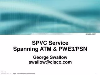
SPVC ServiceSpanning ATM & PWE3/PSNGeorge Swallowswallow@cisco.com
The problem Customer Site Customer Site Customer Site Customer Site PE MPLS ATM Customer Site Customer Site
Requirements • SPVC setup across ATM and PSN • Recovery • No per VC / VP configuration at ATM/PSN boundary • rules out simple splicing • Flexibility in where re-assembly occurs • Minimal or no change to ATM software • Simple solution needed soon
Terminology Customer Site Customer Site ME1 AE1 ATM MPLS PME1 PAE1 AE2 ME2 Key: P - Provider A - ATM M - MPLS E - Edge
Solution Elements / Issues • MPLS / ATM Interface • Addressing • Circuit Identification • Recovery
PWE Identifiers • Two Identifiers for circuit • SAI - Source Attachment Identifier • TAI - Target Attachment Identifier • Structure of SAI, TAI • AGI - Attachment Group Identifier • AII - Attachment Individual Identifier • (In role of source or target AII takes on the name SAII or TAII respectively)
Mismatched Identifiers • ATM • Called Party ATM Address -> Remote Switch & Interface • SPVC IE -> DLCI or VPI/VCI • PWE3 • IP Address -> Remote Switch • TAI -> Interface & DLCI or VPI/VCI
35 00 02 00 00 00 00 00 00 00 IPv4 Port IDP HO-DSP AFI ICP ESI SEL NSAP Format
Mapping Identifiers SPVC Called Party Address SEL IDP HO-DSP ESI DLCI ESI DLCI IP Address Target for LDP FEC TAII
Mapping Identifiers (2) • SPVC IE carries DLCI or VPI / VCI • Two special AGIs are defined to indicate format of the TAII • AGIfr -> <ESI><DLCI> • AGIatm -> <ESI><VPI><VCI> • No further semantics implied • VPI / VCI in SPVC IE does not imply ATM
MPLS / ATM Interface • Interface between ATM and MPLS is AINI or UNI / IISP • MPLS network is modeled as a Multi-homed ATM Host (with lots of addresses) • All AEs advertise the same single NSAP prefix for the MPLS Network • Prefix ::= <IDP for IPv4><IP Net Prefix>
ATM / FR Interworking, FRF5, FRF 8.1 configured at PAE and/or PME Pseudo-wire encapsulation selected on basis of Re-assembly Re-assembly occurs at ME based on presence of AAL5 IE or FD bits Re-assembly & ATM / FR IWF Customer Site Customer Site ME1 AE1 Label Mapping PNNI / Q.2931 UNI ATM MPLS PME1 PAE1 AE2 ME2
Qos configured at PAE and PME Forward & Reverse ATM QoS carried in ATM Signaling Reverse MPLS QoS configured at PME because LDP is uniditectional Forward MPLS QoS inferred from ATM Signaling Quality of Service (QoS) Customer Site Customer Site ME1 AE1 PNNI / Q.2931 UNI ATM MPLS PME1 PAE1 AE2 ME2
Configuration • PMEs: AGIs and (T)AII (note AII indicates both interface and DLCI or VPI/VCI) • PAEs: NSAP and DLCI or VPI/VCI • MEs configured with special AGIs that indicate the further structure of the AII
SPVC Setup • Call is originated from the ATM side • Called Party address • NSAP encoded IP loopback address for MPE + • Interface encoded in ESI • SPVC IE carries DLCI or VPI / VCI
ATM Setup: PAE to ME • PAE uses normal procedures • PNNI determines path to ATM address, selecting an AE • Setup message formatted and sent • Call is routed through a UNI to a ME • ME terminates ATM call
ATM Setup: PAE to ME Customer Site Customer Site ME1 AE1 PNNI / Q.2931 UNI ATM MPLS PME1 PAE1 AE2 ME2 PAE1 uses normal FR SPVC setup
MPLS Setup: ME to MPE • LDP session created to MPE loopback (if not already setup) • TAII created by formatting ESI + DLCI or ESI + VPI/VCI • SAII mapped based on incoming Port & VPI/VCI • Signals L2VPN FEC with AGI + TAII
MPLS Setup: MPE to ME Customer Site Customer Site ME1 AE1 Label Mapping Label Mapping ATM MPLS PME1 PAE1 AE2 ME2 ME1 sends a label for FEC <SAI><TAI> PME1 responds with a label for FEC with values of SAI and TAI reversed
SPVC Setup Completion • PME uses TAII to identify interface and DLCI or VPI/VCI (could be literal or symbolic) • PME responds with reverse setup • ME then completes the ATM call
ATM Setup: ME to PAE Customer Site Customer Site ME1 AE1 Q.2931 / PNNI ATM MPLS PME1 PAE1 AE2 ME2 ME1 sends Connect message to PAE1
Recovery Customer Site Customer Site ME1 AE1 Clear X PTSP LABEL Withdraw ATM Connect Label Mapping PME1 PAE1 Setup MPLS AE2 ME2 PTSP Removes NSAP prefix for MPLS network
Conclusions • Wide deployment of PWE3 will not happen without a tractable transition plan • Proposal places all functions within boxes in PSN (don’t expect ATM vendors to be highly motivated to assist in the transition) • So far ATM / PWE proposals from other organizations has been complex • Needs to be done by the IETF to keep it simple