Flocculation
Flocculation. Overview. Flocculation definition and time and length scales Types of flocculators Mechanical Design Fractal Flocculation Theory applied to hydraulic flocculators CFD analysis of hydraulic flocculators Flocculator Design. What is Flocculation?.

Flocculation
E N D
Presentation Transcript
Overview • Flocculation definition and time and length scales • Types of flocculators • Mechanical Design • Fractal Flocculation Theory applied to hydraulic flocculators • CFD analysis of hydraulic flocculators • Flocculator Design
What is Flocculation? • A process that transforms a turbid suspension of tiny particles into a turbid suspension of big particles! • Requires • Sticky particles (splattered with adhesive nanoglobs) • Successful collisions between particles • Flocs are fractals (“the same from near as from far”) • The goal of flocculation is to reduce the number of colloids (that haven’t been flocculated) • Our goal is to understand why some colloids are always left behind (turbidity after sedimentation)
Mechanical Flocculation • Shear provided by turbulence created by gentle stirring • Turbulence also keeps large flocs from settling so they can grow even larger! • Presumed advantage is that energy dissipation rate can be varied independent of flow rate • Disadvantage is the reactors have low Peclet numbers – potential short circuiting
Recommended G and Gq values:Turbidity or Color Removal (Mechanical flocculators) * Calculated based on G and Gq guidelines + average value assuming viscosity is 1 mm2/s Sincero and Sincero, 1996 Environmental Engineering: A Design Approach G is the wrong parameter… (Cleasby, 1984)
extra Mechanical Design: mixing with paddles Ratio of relative to absolute velocity of paddles Projected area of paddles Drag coefficient “velocity gradient” Reactor volume
extra Mechanical Flocculators? • Waste (a small amount of) electricity • Require unnecessary mechanical components • Have a wide distribution of energy dissipation rates (highest near the paddles) • Have a wide distribution of particle residence times (completely mixed flow reactors)
Ten State Standards http://10statesstandards.com/waterrev2012.pdf • The detention time for floc formation should be at least 30 minutes with consideration to using tapered (i.e., diminishing velocity gradient) flocculation. The flow‑through velocity should be not less than 0.5 nor greater than 1.5 feet per minute. • Agitators shall be driven by variable speed drives with the peripheral speed of paddles ranging from 0.5 to 3.0 feet per second. External, non-submerged motors are preferred. • Flocculation and sedimentation basins shall be as close together as possible. The velocity of flocculated water through pipes or conduits to settling basins shall be not less than 0.5 nor greater than 1.5 feet per second. Allowances must be made to minimize turbulence at bends and changes in direction. • Baffling may be used to provide for flocculation in small plants only after consultation with the reviewing authority. The design should be such that the velocities and flows noted above will be maintained. Hydraulic flocculators allowed only by special permission!
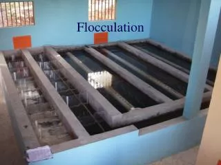
Hydraulic Flocculators • Horizontal baffle • Vertical baffle • Pipe flow • Gravel bed Very low flows and pilot plants A bad idea (cleaning would require a lot of work)
extra Flocculator Geometry Entrance 2 Channels Port between channels Exit Lower Baffles Upper Baffles
extra Why aren’t hydraulic flocculators used more often? • Simple construction means that there aren’t any items that private companies (venders) can sell as specialized components • Consulting firms want to be able to pass the design responsibility off to a vender • The presumed operation flexibility of mechanical flocculators (variable speed motor driving a slow mixing unit) • Poor documentation of design approach for hydraulic flocculators (special permission required to use in the US!) • Using electricity is cool, design innovation is suspect… • Prior to AguaClara we didn’t have a design algorithm based on the fundamental physics
Schulz and Okun (on Hydraulic flocculators) • Recommend velocity between 0.1 and 0.3 m/s • Water must be at least 1 m deep • Distance between baffles at least 45 cm • Q must be greater than 10,000 m3/day (115 L/s) 1 3 2 4 These aren’t universal constants! We need to understand the real constraints so we can scale the designs correctly What length scale could make a dimensionless parameter?
extra AguaClara Flocculator Design Evolution • We began using conventional guidelines based on “velocity gradient” but we were aware that this system was fundamentally incorrect (it doesn’t capture the physics of turbulence) • We were concerned that by using a defective model we could potentially produce defective designs • If the model doesn’t capture the physics, then it won’t scale correctly (and we are designing plants for scales that hadn’t been tested)
extra Edge of Knowledge Alert • Why would we ever think that the baffled flocculators invented over 100 years ago were the optimal design for flocculation? • We are only now beginning to understand the physics of fractal flocculation • We are improving the design of hydraulic flocculators based on our evolving understanding of the physics of flocculation • We have better coagulants, shouldn’t that influence flocculator design?
The Challenge of Flocculation • We would like to know • How the particles make contact to aggregate ______________________________________ • What determines the time required for two flocs to collide? • How strong (or weak) are flocs? • The challenge of the large changes in scale • The Al(OH)3nanoglobs begin at a scale of 100 nanometers • Flocs end at a scale of 100 micrometers Diffusion, velocity gradients, gravity
Hydraulic Flocculation Theory • Colloids and flocs are transported to collide with each other by primarily by viscous shear and turbulent eddies. • Flocs grow in size with each successful collision • Colloids have a hard time attaching to large flocs because the surface shear is too high* • Turbulence is caused by the expansion that results when the water changes direction as it flows around each baffle • Flocculation model and collision potential for reactors with flows characterized by high Peclet numbers • Monroe L. Weber-Shirk,a, and Leonard W. Liona • http://dx.doi.org/10.1016/j.watres.2010.06.026 *hypothesis from 2012!
Exponential growth • How many sequential collisions are required to make a 1 mm particle starting from 1 mm particles? • How much larger in volume is the 1 mm diameter particle? • ____________ ,000,000 ! 1,000
Doubling Collisions • 1 collision 1+1=2 • 2 collisions 2+2=4 • 3 collisions 4+4=8 • 4 collisions 8+8=16 • Number of original particles in the floc = 2n • What is n to obtain 1,000,000,000 = 2n? • n=30 This assumes volume is conserved!
Fractal Dimensions • What happens to the density of a floc as it grows larger? Floc density approaches the density of water because floc includes water diameter of primary particle diameter of floc Fractal dimension Number of primary particles in the floc If volume is conserved, what is DFractal? ____ 3
Fractal Flocculation • Fractal geometry explains the changes in floc density, floc volume fraction, and sedimentation velocity as a function of floc size • The fractal dimension of flocs is approximately 2.3 (based on floc measurements)
Floc Volume Fraction • The fraction of the reactor volume that is occupied by flocs • For fractal dimensions less than 3 the floc volume fraction increases as floc size increases • Use conservation of volume to estimate initial dominates
Primary particle diameter (clay + coagulant) Floc Volume Fraction “super fluffy” flocs Dense flocs
Buoyant Density of Flocs Will these flocs settle faster than the primary particles?
Laminar flow Floc Terminal Velocity Optimal velocity for floc blankets Capture velocity for AguaClara plate settlers Why flocculation is necessary! 1 mm DFractal= 2.3 and d0 = 1 mm shape factor for drag on flocs The model takes into account the changing density of flocs
Analytical Model of the Flocculation Process • The floc porosity increases with floc diameter • The velocity between flocs is a function of whether the separation distance is less or greater than the Kolmogorov scale • The time required per collision is a function of the relative velocity between flocs, the average separation distance between flocs, and the floc size • In the next slides we will explore how to characterize collision time for flocs • We will assume that collisions occur between similar sized flocs. That assumption will need to be evaluated, but it is probably a good assumption for the initial growth of flocs. Are the two flocs in different eddies?
How much water is cleared (filtered) from a floc’s perspective? • Volume cleared is proportional to a collision area defined by a circle with diameter = sum of the floc diameters • Volume cleared is proportional to time • Volume cleared is proportional to the relative velocity between flocs
How much volume must be cleared before a collision occurs? • What is the average volume ofwater “occupied” by a floc? • Need to know floc diameter (dFloc) • And floc volume fraction (fFloc) Floc volumeSuspension volume
Use dimensional analysis to get a relative velocity given a length scale turbulent laminar Viscous range Inertial range L is separation distance Assume linear Re=1 If the flocculator has laminar flow, then this side doesn’t apply and the G, Gq approach applies. The origin of the G notation
Summary for Particle Collisions inertia viscous tc is average time per collision Floc separation distance Is tc a function of d? Yes!
Successful Collision Models inertia viscous Time for one collision Number of successful collisions G is fractional surface coverage of colloids with adhesive nanoglobs dFloc is perhaps mean floc size of flocs that are capturing colloids For completeness we should probably include a correction for hydrodynamic effects that make it difficult for non porous particles to approach closely. This may increase the time for the first few collisions when flocs aren’t very porous
Minimum time to grow from colloid to large floc DFractal= 2.3 d0 = 1 mm e = 6 mW/kg Viscous Inertial 400 s 120 s 20 collisions to grow from 1 mm to 0.4 mm 40 s How much time is required to produce a 0.4 mm floc?
Initial Floc Growth(the 50% solution) • Initial growth phase of flocculation can be modeled with the equations on the previous slide (summing the collision times until the maximum floc size is reached) • The end of the initial growth phase is reached when a significant fraction of the flocs reach the maximum size set by the shear conditions in the reactor and the strength of the bonds holding the flocs together.
Observations: Collision time model • The previous analysis was tracking the time required to make the first big flocs • For a highly turbid suspension it may only take a few seconds to produce visible flocs • This is why successful flocculation can be observed very early in a flocculator • This doesn’t mean that a flocculator with a residence time of 100 s will perform well • We need to track the colloids that are left behind! • Performance is based on _______________ residual turbidity
Remember our Goal? • Introduce pC* • Sloppy parlance… log removal • What is the target effluent turbidity for a water treatment plant? • What is pC* for a water treatment plant treating 300 NTU water?
Tracking the residual turbidity • After the initial production of flocs at their maximum size the interaction of the colloids change • Most of the collisions are ineffective because collisions with flocs that are maximum size are useless and most flocs are their maximum size
Flocculation Model: Integrating and tracking residual turbidity The change in colloid concentration with respect to the potential for a successful collision is proportional to the colloid concentration (the fraction of the colloids swept up is constant for a given number of collisions) Separate variables Integrate from initial colloid concentration to current colloid concentration Classic first order reaction with number of successful collisions replacing time
Laminar Flow Cases Only colloids can collide effectively (big flocs are useless) Floc volume fraction that matters for successful collisions is the colloid (small floc) fraction Colloids can attach to all flocs Floc volume fraction is a function of floc size (d) (which is a function of the reaction progression and shear conditions in the reactor
Comparison of Flocculation Hypotheses If colloids could aggregate with all of the flocs then colloids would aggregate VERY rapidly Ten state standards 30 minute flocculation time. The graph is laminar flow case, full scale flocculators are turbulent flow. 100 NTU clay suspension, G = 0.1 Show that pC* is proportional to time for “everything aggregates” model
Coiled Tube Flocculation Residual Turbidity Analyzer Dr. Karen Swetland Dissertation research
Data is consistent with the hypothesis that large flocs are useless Alum PACl Model over predicts performance because it doesn’t account for time required for first settleable flocs to form
Laminar Flocculation - Sedimentation Model Sedimentation velocity of ??? Sedimentation tank capture velocity Floc volume fraction Flocculator/sedimentation performance group. (Bigger = higher performance) Flocculation time It’s about collisions!!!!!! Velocity gradient Fractional surface coverage of colloid by coagulant A big step in creating an overall performance model for water treatment! New Insight?
Solving for pC*: Lambert W or ProductLog Function (Laminar flow) Use Wolframalpha to solve for C* W is the Lambert W function Log is base 10
Turbulent Flow Case Only colloids can collide and attach effectively Colloids can attach to all flocs
Turbulent Flow Flocculator:“Big Flocs are useless” hypothesis After the big flocs become non reactive, then the average separation distance between the remaining flocs is larger and thus the collisions between active particles is dominated by inertia. Ten state standards 30 minute flocculation time. The predicted performance is quite similar given a wide range of influent turbidities The predictions seem reasonable • = 0.1 for these plots • e = 2.6 mW/kg
Turbulent Flow Flocculator: Colloids can attach to all flocs hypothesis Here the separation distance between reactive flocs might be less than the Kolmogorov length scale Ten state standards 30 minute flocculation time. The predicted performance is quite different from what we observe. High turbidity would be very easy to treat if this hypothesis were true! Flocculators would be tiny! For these plots G= 0.1 e= 2.6 mW/kg pC* proportional to time
Solving for pC*: Lambert W or ProductLog (Turbulent Flow) Use Wolframalpha to solve for C* W is the Lambert W function Log is base 10
Lambert W Function • Performance varies very little over wide range of inputs. • Diminishing returns on investment
Turbulent Flocculation Sedimentation Model Flocculation time Lambert W Function Energy dissipation rate Sedimentation velocity of ??? Sedimentation tank capture velocity -log(fraction remaining) Characteristic colloid size Initial floc volume fraction Fractional surface coverage of colloid by coagulant G What does the plant operator control? ________ What does the engineer control? __________