Download
1 / 21
210 likes | 232 Vues
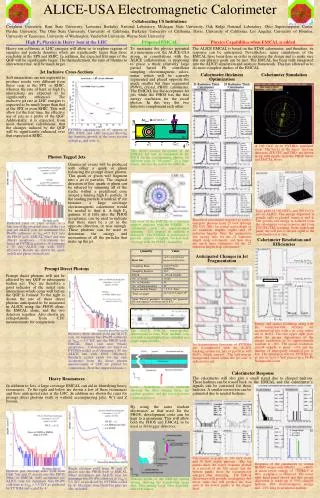
This article discusses the ALICE Electromagnetic Calorimeter (EMCal) and its importance in studying jet fragmentation in high multiplicity collisions at the Large Hadron Collider (LHC). Topics covered include the construction and installation of the EMCal, its readout system, and the triggering algorithms used for jet identification.

E N D
The ALICE Electromagnetic Calorimeter Terry C. Awes Oak Ridge National Laboratory For the ALICE Collaboration 11th Pisa Meeting on Advanced Detectors La Biodola, Italy May 25-29, 2009
The ALICE Experiment • Pb+Pb @LHC emphasis • High multiplicities, soft particles T.Awes, ORNL
Jets in ALICE Jet “Quenching” at RHIC • Hard-scattered partons interact strongly with the medium and lose energy resulting in softer fragmentation • Probe of medium • Important at LHC due to increased jet cross section • To study jet fragmentation in detail requires EMCal • Measure EM energy to provide total jet energy (or recoil ) • Provide jet (or ) trigger T.Awes, ORNL
The Electromagnetic Calorimeter • Funding approval: Feb. 2008 (~ALICE Upgrade: US, Italy, France, CERN, Finland) • 7+2/3 US Super-Modules (SM) • 3 EU SMs (Italy and France) • Construct and Install 2008-2011 Lead-Scintillator Sampling Calorimeter = 1.4, =107o Shashlik Geometry, APD Photosensor 12288 Towers T.Awes, ORNL
EMCal Support Structure T.Awes, ORNL
EMCal Installation in ALICE T.Awes, ORNL
Arrival of First EMCal SM March 2009 ~1 year after funding ~ 8 tonnes T.Awes, ORNL
Installation of EMCal (SM #2) T.Awes, ORNL
EMCal Assembly • 3072 identical modules, 2x2 towers • 1.5o taper in • Tower granularity = = 0.014 • 20.1 X0 • 77 layers Pb:Sc = 1.44 : 1.76 mm 12 Modules per strip module 24 Strip Modules per Super Module T.Awes, ORNL
EMCal Readout Preamplifier+APD • 4 6x6 cm2 towers/module • WLS fiber readout on 1cm grid • 5x5 mm2 Hamamatsu S8148 APD • ~4.5 photo-electrons/MeV at gain M=1 • Operated at nominal M=30 • Fullscale Energy = 250 GeV T.Awes, ORNL
EMCal SM Readout Assembly • Signal Cables • 4 modules each • 16 towers • 2 per FEE • 2 FEE crates per SM • 1 Readout+Detector Control Unit (RCU+DCS) per FEE crate • Control via ethernet. Readout via fiber optic (ALICE DDL standard) • 2 GTL Readout/Control Bus per FEE crate • 9 FEE cards + 1 Trigger Region Unit (TRU) card per GTL bus • 36 + 1 FEE cards + 3 TRU per SM LED fibers (monitoring) FEE cards RCU+DCS GTL Bus T.Awes, ORNL
EMCal Readout Overview Same Readout for TPC/PHOS/EMCal ALICE items • 9 FEE + 1 Trigger Region Unit (TRU) setup/readout via GTL bus. • Readout Control Unit (RCU)controls FEE on up to 2 GTL bus branches. • Detector Control System (DCS) RCU daughter cardfor FEE setup (e.g. APD bias) • Data to DAQ via Detector Data Link on RCU- passed to High Level Trigger. T.Awes, ORNL
EMCal FEE • 32 channels/FEE Card • Individual APD Bias control (between 210 and 400V) • Dual shapers (CR-2RC) for each channel for increased dynamic range. E.g. x16 gain difference. • EMCal uses 100ns shaping time • Shaper output flash digitized with ALice Tpc ReadOut (ALTRO) chip: 10-bits, Sampling rate of 10MHz, multi-event buffering. • 14-bits effective dynamic range • Trigger capability with Analog sum of fast shaped (100ns) 2x2 adjacent towers (1 module), output to TRU trigger board to perform trigger logic. • Readout via GTL backplane (same as ALICE TPC), same Readout Control Designed by: H. Muller, CERN. See Y.Wang, FEE poster session, Thurs. 16:00 H.Muller, et al., NIM A565 (2006) 768. T.Awes, ORNL
EMCal Trigger Overview • L0 - required at Central Trigger Processor within 800ns • Form trigger primatives • 2x2 towers analog summed in FEE (FastOR) • Output (via cable) to Trigger Region Unit where • flash digitized, pedestals subtracted, time-summed (integrated) • L0 algorithm (“activity” in EMCal) runs in TRU • Overlapping 2x2 FastORs digitally summed • Peak detect and Thresholds applied (low energy - EMCal activity) • Valid L0 triggers passed to Summary Trigger Unit (STU) to be OR’d • Upon accepted L0 from ALICE CTP • Pass FastOR time-summed data to STU for L1 algorithms • If desired, store trigger primative FastOR FADC samples, via GTL bus • L1 - input from all TRUs to STU. L1 required at CTP within 5 s • L1 High energy EM shower (, 0, electron) • Form overlapping 2x2 FastOR digital sums • Multiplicity (centrality) dependent Thresholds applied (V0 detector input) • L1 Jet trigger • Form overlapping NxN FastOR digital sums (where N is large) • Multiplicity (centrality) dependent Thresholds applied (V0 detector input) T.Awes, ORNL
EMCal Trigger Region Unit • Output: 4 LVDS lines to STU - L0, 2 serial data, 1 serial clock • Raw 2x2 trigger FADC data samples can be recorded as FEE data • Up to 112 2x2 tower (= 1 module) analog sums from FEE digitized (12-bits) at 40MHz • L0 algorithm: overlapping 4x4 towers with low threshold (VIRTEX-5 FPGA) Designed by: H. Muller, CERN. See FEE poster session, Thurs. 16:00 T.Awes, ORNL
Summary Trigger Unit 32 TRU inputs 4 TRU inputs 4 TRU inputs Trigger outputs V0 interface DDL interface DCS interface L0 in TTCRq • LHC clock via TTC for LVDS serial data transmission from up to 40 TRUs • FastOR data transmitted serially at 2x400 Mbits/s • L0, L1 Trigger pattern data stored as ALICE DDL data packet Virtex-5 FPGA Designed by: O.Bourrion, LPSC, Grenoble T.Awes, ORNL
EMCal Beam Test Results • Beam tests with 4x4 Module array (8x8 towers) • First Prototypes tested at FNAL fall 2005 • Pre-production Modules+FEE tested at CERN PS and SPS 2007 • Electron, hadron data 0.5 - 100 GeV/c • NIM paper in preparation T.Awes, ORNL
APD Gain Monitoring • Measure Temperature field at 8 points on SM • Readout via ALICE slow control (ELMB system) • LED pulser system on SM to track gains • One ultra-bright blue LED per strip module • Custom LED driver system with 3x8 LED channels • Photodiode reference to monitor LED light • Photodiodes read out with 1 extra FEE card LED system: LED+photodiode for each strip LED signals in towers ~ 5 GeV T.Awes, ORNL
EMCal Cosmics pre-Calibration • After SM assembly and test completed calibrate SM with cosmics • Overnight cosmics runs with scintillator triggers • OR of all (Top AND Bottom) scintillator pairs • Record scintillator ADC and Time • Apply Time difference cut to locate within ~ 1 module • Apply EMCal tower isolation cut to locate mip to single tower • Design goal (trigger): Relative calibration to within better than 10% • Final calibrations performed in situ with 0 mass (a la PHENIX) After 2nd gain adjustment iteration MIP distribution rms<3% 2nd iteration result MIP ADC peaks (384 towers) Initial M=30 result T.Awes, ORNL
EMCal in ALICE • 2 EMCal SMs installed and being commissioned • Pedestal and LED data have been taken • Same performance as during calibrations • 2 additional EMCal SMs to be installed July ‘09 • EMCal will be nearly 40% installed for 2009 LHC run High Gain Ped. <rms>=0.75 Low Gain 2 0 1 ADC count T.Awes, ORNL
Summary • EMCal addition to ALICE will enhance jet studies • EM component of jets, -jet, 0 measurement, electron identification • Provide L0 trigger, L1 and jet trigger • ALICE EMCal will be ~40% installed for first collisions at LHC • 2 SMs installed already, 2 more SMs in July • Commissioning will be completed during ALICE cosmics run • Ready for physics with first collisions T.Awes, ORNL