Trouble Shooting
Trouble Shooting. 1. No Power. 9. Hard Drive Test Error. 2. Battery Can not Be Charged. 10. CD-ROM Driver Test Error. 3. No Display. 11. USB Port Test Error. 4. LCD No Display or Picture Abnormal. 12. PC Card Socket Test Error. 5. External Monitor No Display or Color Abnormal.

Trouble Shooting
E N D
Presentation Transcript
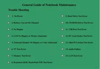
Trouble Shooting 1. No Power 9. Hard Drive Test Error 2. Battery Can not Be Charged 10. CD-ROM Driver Test Error 3. No Display 11. USB Port Test Error 4. LCD No Display or Picture Abnormal 12. PC Card Socket Test Error 5. External Monitor No Display or Color Abnormal 13. Mini-PCI Socket Test Error 6. TV Test Error 14. Audio Failure 7. Memory Test Error 15. LAN Test Error 8. Keyboard (K/B) Touch-Pad (T/P) Test Error
*1:No power definition Base on ACPI Spec. We define the no power as while we press the power button, the system can’t leave S5 status or none the PG signal send out from power supply. Judge condition: • Check whether there are any voltage feedback control to turn off the power. • Check whether no CPU power will cause system can’t leave S5 status. If there are not any diagram match these condition, we should stop analyzing the schematic in power supply sending out the PG signal. If yes, we should add the effected analysis into no power chapter. *2:No display definition Base on the digital IC three basic working conditions: working power, reset, Clock. We define the no display as while system leave S5 status but can’t get into S0 status. Judge condition: • Check which power will cause no display. • Check which reset signal will cause no display. • Check which Clock signal will cause no display Base on these three conditions to analyze the schematic and edit the no display chapter. • S5: Soft Off • S0: Working Keyword: For detail please refer the ACPI specification
Example for Main Voltage Map When power button is pressed ,nothing happens ,power indicator does not light up. L7 +3.3VDACVDD L507 +NB_AVDD1 PF501,PD501 PL501,PL502 L509 PD503 PU6,PD4,PR20 PU502 L508 Power In PWR_VDDIN +5VA +3VA +3VA_KBC +NB_AVDD2 PJ501 PQ502 PR501 PR502 L1 Q1 PD502 PU5 +3VS_LCD +LCDVCC +3VS (Discharge) PF503,PU14,PU15, PD6~PD9,PQ508,PQ507,PQ509, PQ510,PL508,PL509 U517 +VCCA PD504 PU12 ADINP D/VMAIN +CPU_CORE +2.5VDDA PU10,PQ13,PD5 PF502,PL504 PU4,PD2 PL503,PQ503,PL506PR507,JO3,JO4,PJO2 PU8 PD507PU501 PL507PR511PD3 +1.2VLDTA +3VSB L513 PF1 PL1 PL2 PQ6 PQ7 +3VS_USB (Charge) PU1 L25 +3V +3V_MII L521 +3V_LAN BATTERY PU3 L21,L512 (Discharge) +5VS +5VS_CDROM L30,L520 +5VS_HD PQ504,PQ505,PL506,PD1 PR510,JO5,JO6,PJO1 L530,R712 +5VSB AVDD L532,L33 +AMP_5V U504 USB0VCC5 PF504,PJO505,PU16,PU17,PU18PD508,PD11,PL510,PR91,PR96 PD12,JO503,JO504,JO505 PU2 U4 +5V USB1VCC5 U506 +2.5VSB USB2VCC5 U7 USB3VCC5
1 No Power When power button is pressed ,nothing happens ,power indicator does not light up. No Power Check the following signals if they are correct using an oscilloscope to check one at a time and test. Battery Is the Notebook connected to power (Either AC adaptor or battery)? Signal No Connect AC adaptor or battery BATT BATT_T BATT_V D/VMAIN ADINP ADINP_1 ADINP_2 ADEN# Yes Where From Power Source Problem(First use AC to power it) Try another known good battery or AC adapter. Check the following signals if they are correct using an oscilloscope to check one at a time and test. Replace the faulty AC adaptor or Battery. Yes Power OK? AC Adaptor No Signal D/VMAIN PWR_VDDIN LEARNING +5VA +3VA Board-level Troubleshooting Replace Motherboard
2 Battery Can not Be Charged When the battery is installed but the battery status indicate LED display abnormal. Battery can not Charge Board-level Troubleshooting Is the notebook connected to power (AC adaptor)? No Connect AC adaptor. Check the following signals one at a time and Test. Replace Motherboard Yes Signal 1. Make sure that the battery is good. 2. Make sure that the battery is installed properly. ADINP ADINP_[1,2] LI_OVP I_LIMIT CHG_I BATT BATT_V BATT_T BATT_C BATT_D BATT_DEAD Yes Battery charge OK? Correct it. No
No Display 3 No Display There is no display on both LCD and VGA monitor after power on although the LCD and monitor is known-good. Monitor or LCD module OK? No Replace monitor or LCD. Board-level Troubleshooting Yes Make sure that CPU module, DIMM memory are installed Properly. If 378 Port Have error code Yes According error Cord to repair Yes Display OK? Correct it. Replace Motherboard No No 1. Try another known good CPU module, DIMM module And BIOS. 2. Remove all of I/O device (HDD, CD-ROM…….) from motherboard except LCD or monitor. Check system clock and reset circuit. 1. Replace faulty part. 2. Connect the I/O device to the M/B one at a time to find out which part is causing the problem. Yes Display OK? To be continued Clock and reset checking No
VGA Controller Failure Replace Motherboard 4 LCD No Display or Picture Abnormal There is no display or picture abnormal on LCD or monitor. Board-level Troubleshooting 1. Confirm LCD is good and check the cable are connected properly. 2. Try another known good LCD One of the following signals one at a time and test. Yes Replace faulty LCD Display OK? Signals: No +3VS D/VMAIN +LCDVCC IXOUT2 LCD_ID[0:2] TXOUT[0:2]+ TXOUT[0:2]- TXOUTCLK1+ TXOUTCLK1- ENPBLT ENAVDD BLADJ Remove all the I/O device & cable from motherboard except extended LCD. Connect the I/O device & cable to the M/B one at a time to find out which part is causing the problem. Yes Display OK? No
VGA Controller Failure Replace Motherboard 5 External Monitor No Display or Color Abnormal There is no display or picture abnormal on monitor. 1. Confirm monitor is good and check the cable are connected properly. 2. Try another known good monitor Board-level Troubleshooting Yes Replace faulty monitor. Display OK? to check the following signals one at a time and test. No Signals: Remove all the I/O device & cable from motherboard except extended monitor. +5VS CRT_RED CRT_GREEN CRT_BLUE CRT_DDDA CRT_HSYNC CRT_VSYNC CRT_DDCK Connect the I/O device & cable to the M/B one at a time to find out which part is causing the problem. Yes Display OK? No
TV Controller Failure Display OK? Replace Motherboard. 6 TV Test Error There is no display or picture abnormal on TV. Board-level Troubleshooting Confirm TV is good and check the cable are connected properly. use an oscilloscope to check the following signals Yes Replace faulty cable Signals: No +3VS PCI_RESET# TVD[0:11] TVCLK TVCLKR SPCLK1 SPD1 TVHS TVVS TV_14M
7 Memory Test Error Extend DDRAM is failure or system hangs up. Memory Test Error 1. If your system installed with expansion DDR SO-DIMM module then check them for proper installation. 2. Make sure that your DDR SO-DIMM sockets are OK. 3. Then try another known good DDR SO-DIMM modules. Board-level Troubleshooting Use an oscilloscope to check the signals one at a time. Yes Test OK? Replace the faulty DDR SDRAM module. Signals: No +2.5V +DDR_VREF CKEA CKEB SMBDATA SMBCLK DDR_BAA [0,1] DDR_BAB [0,1] MEMADD_A[0:13] MEMADD_B[0:13] DDR_CLK [0,1,4,5,6,7] DDR_CLK [0,1,4,5,6,7]# DDR_WEA# DDR_WEB# CPU_CS[0:3]# DDR_RASA# DDR_RASB# DDR_CASA# DDR_CASB# If your system host bus clock running at 266/333/400 MHZ then make sure that DDR SO-DIMM module meet require of PC 2100/2700/3200. Replace Motherboard Yes Test OK? Replace the faulty DDR SDRAM module. No
Keyboard or Touch-Pad Test Error Replace Motherboard 8 Keyboard (K/B) Touch-Pad (T/P) Test Error Error message of keyboard or touch-pad failure is shown or any key does not work. Board-level Troubleshooting Is K/B or T/P cable connected to notebook properly? Yes Correct it. use an oscilloscope to check the signals one at a time and test after each replacement. No Signals +3VA +3VA_KBC LPC_LAD[0:3] SERIRQ PCI_KBC_CLK KO[0:15] KI[0:7] T_CLK T_DATA XIN XOUT Try another known good Keyboard or Touch-pad.(Internal or external) Replace the faulty Keyboard or Touch-Pad Yes Test Ok? No
Replace Motherboard 9 Hard Drive Test Error Either an error message is shown, or the driver motor continues spinning, while reading data is from or writing data is to hard drive. Hard Driver Test Error Board-level Troubleshooting 1. Check if BIOS setup is OK? 2. Try another working drive. use an oscilloscope to check the signals one at a time Yes Re-boot OK? Replace the faulty parts. Signals: No +5VS +5VS_HD PCI_RESET# IDE_RST# IDE_D_PDD[0:15] IDE_D_PDDREQ IDE_D_PDIOW# IDE_D_PDIOR# IDE_D_IORDY IDE_D_PDDACK# IDE_D_IRQ14 IDE_D_PDA[0:2] IDE_D_PDCS1# IDE_D_PDIAG IDE_D_PDCS3# Check the system drive for proper installation. Yes Re - Test OK? End No
Replace Motherboard 10 CD-ROM Drive Test Error An error message is shown when reading data from CD-ROM drive. CD-ROM Driver Test Error Board-level Troubleshooting 1. Try another known good compact disk. 2. Check install for correctly. use an oscilloscope to check the signals one at a time Yes Test OK? Replace the faulty parts. Signals: +5VS +5VS_CDROM PCI_RESET# IDE_RST# IDE_D_SDD[0:15] IDE_D_SDDREQ IDE_D_SDIOW# IDE_D_SDIOR# IDE_D_IORDY IDE_D_SDDACK# IDE_D_IRQ15 IDE_D_SDA[0:2] IDE_D_SDCS1# IDE_D_SDIAG IDE_D_SDCS3# No Check the CD-ROM driver for proper installation. Yes Re - Test OK? End No
USB Test Error 11 USB Port Test Error An error occurs when a USB I/O device is installed. Board-level Troubleshooting Check if the USB device is installed properly. use an oscilloscope to check the following signal one at a time Yes Test OK? Correct it Replace Motherboard No Signals: +5V +2.5V +2.5V_USB +3V +3V_USB +VCC_USB_0 +VCC_USB_1 +VCC_USB_2 +VCC_USB_3 USBP[0:3]+ USBP[0:3]- USB0VCC5 USB1VCC5 USB2VCC5 USB3VCC5 USBCLK_SB USB_OC[0:3]# Replace another known good USB device. Yes Re-test OK? Correct it No
PC-Card Socket Test Error 12 PC-Card Socket Test Error An error occurs when a PC card device is installed. Board-level Troubleshooting 1. Check if the PC CARD device is installed properly. 2. Confirm PC card driver is installed ok. use an oscilloscope to check the following signal one at a time. Yes Test OK? Replace Motherboard Correct it No Signals +3VS VCCA VPPA PCI_AD[0:31] PCI_RESET# PCI_C/BE#[0:3] PCI_FRAME# PCI_IRDY# PCI_TRDY# PCI_DEVSEL# PCI_STOP# PCI_INTB# PCI_GNT0# PCI_SERR# PCI_PERR# PCICLK_CARD PCI_PAR PCI_REQ0# CLKRUN# PCI_LOCK# SERIRQ Try another known good PC card device. Yes Re-test OK? Change the faulty part then end. No
Mini-PCI Socket Test Error 13 Mini-PCI Socket Test Error An error occurs when a PC card device is installed. Board-level Troubleshooting 1. Check if the Mini-PCI CARD device is installed properly. 2. Confirm Mini-PCI driver is installed ok. use an oscilloscope to check the following signal one at a time Yes Test OK? Replace Motherboard Correct it No Signals Try another known good Mini-PCI card device. +5VS +3VS PCI_AD[0:31] LPC_LAD[0:3] PCI_C/BE#[0:3] MINIPCI_PD PCI_INTC# PCI_MINI_CLK PCI_REQ2# PCI_IRDY# CLKRUN# PCI_SERR# PCI_PERR# PCI_INTD# PCI_INTC# PCI_RESET# PCI_GNT2# PCI_PAR PCI_FRAME# PCI_TRDY# PCI_STOP# PCI_DEVSEL# Yes Change the faulty part then end. Re-test OK? No
Audio Drive Failure Replace Motherboard 14 Audio Failure No sound from speaker after audio driver is installed. Board-level Troubleshooting 1. Check if speaker cables are connected properly. 2. Make sure all the drivers are installed properly. use an oscilloscope to check the following signal one at a time Yes Test OK? Correct it. No Signals 1. Try another known good speaker,CD-ROM. 2. Exchange another known good Audio/touch pad/card Read board. +5VS +AMP_5V AOUT_R AOUT_L ROUT+ ROUT- LOUT+ LOUT- LINE_OUT_L LINE_OUT_R SPK_OFF AVDD MIC_INT MIC_EXT Yes Re-test OK? Correct it. No
Replace Motherboard 15 LAN Test Error An error occurs when a LAN device is installed. LAN Test Error Board-level Troubleshooting 1. Check if the driver is installed properly. 2. Check if the notebook connect with the LAN properly. use an oscilloscope to check the following signal one at a time and Test. Signals Yes Test OK? Correct it. +3V +3V_LAN LAN_MTXD[0:3] LAN_MRXD[0:3] LAN_MRXDV LAN_MRXER LAN_MRXC LAN_MTXE LAN_MTXC LAN_DCLK LAN_DADAIO LAN_COL LAN_CRS LAN_TXP LAN_TXN LAN_RXP LAN_RXN No