Download
1 / 33
330 likes | 541 Vues
ENG224 INFORMATION TECHNOLOGY – Part I. 7. Ethernet – A Case Study of Physical and Data Link Layer. 7. Ethernet A Case study of Physical and Data Link Layer . ENG224 INFORMATION TECHNOLOGY – Part I. 7. Ethernet – A Case Study of Physical and Data Link Layer. Origin of Ethernet.

E N D
ENG224 INFORMATION TECHNOLOGY – Part I 7. Ethernet – A Case Study of Physical and Data Link Layer 7. EthernetA Case study ofPhysical and Data Link Layer
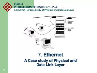
ENG224 INFORMATION TECHNOLOGY – Part I 7. Ethernet – A Case Study of Physical and Data Link Layer Origin of Ethernet • Found by Xerox Palo Alto Research Center (PARC) in 1975 • Original designed as a 2.94 Mbps system to connect 100 computers on a 1 km cable • Later, Xerox, Intel and DEC drew up a standard support 10 Mbps • Basis for the IEEE’s 802.3 specification
ENG224 INFORMATION TECHNOLOGY – Part I 7. Ethernet – A Case Study of Physical and Data Link Layer Ethernet Basics • Topologies Linear bus, Star bus • Signaling Mainly baseband (digital) • Access method CSMA/CD • Specifications IEEE 802.3 • Transfer speed 10 Mbps, 100 Mbps, or above • Cable types Coaxial cables, UTP
ENG224 INFORMATION TECHNOLOGY – Part I 7. Ethernet – A Case Study of Physical and Data Link Layer Ethernet Frame Format Preamble Des. Add Sour. Add Type Data FCS 8 Bytes 6 Bytes 6 Bytes 2 Bytes 46 - 1500 Bytes 4 Bytes • Preamble: For synchronization • Des. Add: Destination address • Sour. Add: Source address • FCS: Frame Check Sequence
ENG224 INFORMATION TECHNOLOGY – Part I 7. Ethernet – A Case Study of Physical and Data Link Layer Frame operation P DA = 2 SA = 6 T DATA FCS
ENG224 INFORMATION TECHNOLOGY – Part I 7. Ethernet – A Case Study of Physical and Data Link Layer Ethernet Address 00 00 E2 15 1A CA
ENG224 INFORMATION TECHNOLOGY – Part I 7. Ethernet – A Case Study of Physical and Data Link Layer Ethernet addresses are 48 bits long. Ethernet addresses are governed by IEEE and are usually imprinted on Ethernet cards when the cards are manufactured. Examples of Manufacturer IDs Cisco : 00-00-0C- 3Com : 00-60-8C- : 00-60-09- : 00-60-08- Xircom : 00-80-C7- IBM : 08-00-5A- Sun : 08-00-20- Nokia : 00-40-43-
ENG224 INFORMATION TECHNOLOGY – Part I 7. Ethernet – A Case Study of Physical and Data Link Layer IEEE 802.3 Frame Format Preamble Des. Add Sour. Add Length Data FCS 7 Bytes 1 Byte 2/6 Bytes 2/6 Bytes 2 Bytes 46 - 1500 Bytes 4 Bytes Original Ethernet II Frame Format Preamble Des. Add Sour. Add Type Data FCS 8 Bytes 6 Bytes 6 Bytes 2 Bytes 46 - 1500 Bytes 4 Bytes
ENG224 INFORMATION TECHNOLOGY – Part I 7. Ethernet – A Case Study of Physical and Data Link Layer Check the line If no packet, OK to transmit Access Method - CSMA/CD • Carrier Sense Multiple Access / Collision Detection
ENG224 INFORMATION TECHNOLOGY – Part I 7. Ethernet – A Case Study of Physical and Data Link Layer Check the line Find no packet OK to transmit Check the line Find no packet OK to transmit • If computers are too far away, carrier detection before transmission doesn’t always work Long distance
ENG224 INFORMATION TECHNOLOGY – Part I 7. Ethernet – A Case Study of Physical and Data Link Layer Listen & Compare Listen & Compare • After transmit, keep listening to the line • Compare the data on the line with the ones being transmitted • If different, stop transmission immediately (to minimize wasted time ― because there is no use continuing) • Wait for a random time and try all over again
ENG224 INFORMATION TECHNOLOGY – Part I 7. Ethernet – A Case Study of Physical and Data Link Layer CSMA/CD ― Design Considerations • More computers on the LAN, higher chance of collisions • Retransmission may result in collision again and cause further delay • As the result, the network becomes standstill • Hence, Ethernet is suitable for low traffic networks
ENG224 INFORMATION TECHNOLOGY – Part I 7. Ethernet – A Case Study of Physical and Data Link Layer 10 Mbps IEEE Standards - 10BaseT • 10BaseT 10 Mbps, baseband, over Twisted-pair cable • Running Ethernet over twisted-pair wiring as specified by IEEE 802.3 • Configure in a star pattern Unshielded twisted-pair RJ-45 Plug and Socket
ENG224 INFORMATION TECHNOLOGY – Part I 7. Ethernet – A Case Study of Physical and Data Link Layer • Baseband Transmission • Entire channel is used to transmit a single digital signal • Complete bandwidth of the cable is used by a single signal • The transmission distance is shorter • The electrical interference is lower • Broadband Transmission • Use analog signaling and a range of frequencies • Continuous signals flow in the form of waves • Support multiple analog transmission (channels) Baseband Transmission Broadband Transmission Modem Network Card
ENG224 INFORMATION TECHNOLOGY – Part I 7. Ethernet – A Case Study of Physical and Data Link Layer • Twisted Pair Cables • Unshielded Twisted Pair Cable (UTP) • most popular • maximum length 100 m • more susceptible to noise • EIA/TIA 568 Commercial Building Wire Standard
ENG224 INFORMATION TECHNOLOGY – Part I 7. Ethernet – A Case Study of Physical and Data Link Layer • Shielded Twisted Pair Cable (STP) • Shielding to reduce crosstalk • Crosstalk: signal from one line getting mixed with signals from another line • Connector • RJ-45 computer connector (8 wires)
ENG224 INFORMATION TECHNOLOGY – Part I 7. Ethernet – A Case Study of Physical and Data Link Layer Case 1 T568B T568A Cross-over cable Case 3 Case 2 Wall plate Cross-over cable T568B T568B Hub Straight through cable Straight through cable
ENG224 INFORMATION TECHNOLOGY – Part I 7. Ethernet – A Case Study of Physical and Data Link Layer A typical 10BaseT network Backbone
ENG224 INFORMATION TECHNOLOGY – Part I 7. Ethernet – A Case Study of Physical and Data Link Layer 10BaseT Summary • Cable Category 3, 4, or 5 UTP • Connectors RJ-45 at cable ends • Max. distance between 100 m. (328’) computer to hub • Backbones for hubs Coaxial or fibre-optic • Total computers per LAN 1024
ENG224 INFORMATION TECHNOLOGY – Part I 7. Ethernet – A Case Study of Physical and Data Link Layer Pros and Cons of 10BaseT • Advantages • Easier to manage • Scalable • Cable itself is relatively inexpensive • Drawback • High attenuation leads to short segment length • Need good infrastructure planning beforehand
ENG224 INFORMATION TECHNOLOGY – Part I 7. Ethernet – A Case Study of Physical and Data Link Layer 10 Mbps IEEE Standards - 10Base2 • Called 10Base2 because it carries signal roughly 2 times 100 m (actually 185 m) • Use thin coaxial cable, thinnet • Configure in a linear bus pattern
ENG224 INFORMATION TECHNOLOGY – Part I 7. Ethernet – A Case Study of Physical and Data Link Layer • Both end of a segment needed to be terminated to avoid energy bounce back • Can introduce collision if without termination • To reduce interference, can ground the terminator • Never ground both ends as there can be voltage difference in both ends
ENG224 INFORMATION TECHNOLOGY – Part I 7. Ethernet – A Case Study of Physical and Data Link Layer A typical 10Base2 network Follow 5-4-3 rule
ENG224 INFORMATION TECHNOLOGY – Part I 7. Ethernet – A Case Study of Physical and Data Link Layer 10Base2 Summary • Max. segment length 185 m (607’) • Minimum distance between 0.5 m (1.5’) • T joints • Connectors to NIC BNC T connector • Cable Coaxial, e.g. RG-58 • Follow 5-4-3 rule • Max. total network length 925 m (3035’) • Computers per segment 30
ENG224 INFORMATION TECHNOLOGY – Part I 7. Ethernet – A Case Study of Physical and Data Link Layer Pros and Cons of 10Base2 • Advantages • Easy to install • Easy to configure • Drawback • Difficult to maintain • Cable itself is expensive • Not extendable to 100 based systems
ENG224 INFORMATION TECHNOLOGY – Part I 7. Ethernet – A Case Study of Physical and Data Link Layer 100 Mbps Networks • Multimedia network applications push the development of faster networks • Several Ethernet standards exist: • 100BaseVG-AnyLAN Ethernet • 100BaseX Ethernet (Fast Ethernet) • 10 times faster than 10BaseX systems • Compatible with existing cabling systems
ENG224 INFORMATION TECHNOLOGY – Part I 7. Ethernet – A Case Study of Physical and Data Link Layer 100VG-AnyLAN • Originally developed by Hewlett-Packard • Currently being refined and ratified by IEEE 802.12 committee • Specifications: • Minimum data rate 100 Mbps • Support a cascaded star topology over cat.3, 4, and 5 twisted-pair and fiber-optic cables • Use demand priority access method • Support for both Ethernet frames and Token Ring packets
ENG224 INFORMATION TECHNOLOGY – Part I 7. Ethernet – A Case Study of Physical and Data Link Layer Star bus Topology • Max distance from hub to computer: 250 m
ENG224 INFORMATION TECHNOLOGY – Part I 7. Ethernet – A Case Study of Physical and Data Link Layer Demand priority access method • Hub continuously scans in a round-robin way for requests from computer • Each node has two priorities • High: for multimedia data • Low: for normal data
ENG224 INFORMATION TECHNOLOGY – Part I 7. Ethernet – A Case Study of Physical and Data Link Layer • If both high and low priority packets are pending to transfer, send high priority first • Resume to serve low priority packets if all high priority packets have been served
ENG224 INFORMATION TECHNOLOGY – Part I 7. Ethernet – A Case Study of Physical and Data Link Layer 100BaseX Ethernet • Also calledFast Ethernet • Specified by IEEE 802.3 addendum • Extension to the existing Ethernet standard • Run on UTP Cat.5 cable and use CSMA/CD in a star wired bus • Can be easily plug-and-play over the existing systems
ENG224 INFORMATION TECHNOLOGY – Part I 7. Ethernet – A Case Study of Physical and Data Link Layer Value Represent Actual Meaning 100 Transmission 100 Mbps speed Base Signal type Baseband T4 Cable type 4 telephone-grade twisted -pair cable (cat. 3,4,5) TX Cable type 2 data-grade twisted-pair cable (cat. 5) FX Cable type Fiber-optic link using 2 strands of fiber cable
ENG224 INFORMATION TECHNOLOGY – Part I 7. Ethernet – A Case Study of Physical and Data Link Layer Comparison with 10BaseT • Transmit on 3 pairs vs. 1 pair x 3.00 • 8B6T coding instead of Manchester x 2.65 • 20 to 25 MHz clock increase x 1.25 • 10.00