Chapter 7 OSI Data Link Layer
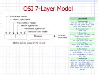
Chapter 7 OSI Data Link Layer. OSI Data Link Layer. Accessing the Media. OSI Data Link Layer. Provides the user interface. Segmentation and managing communications. Organize data for network transfer. Exchange data over common media. Supporting and Connecting to Upper Layer.


Chapter 7 OSI Data Link Layer
E N D
Presentation Transcript
Chapter 7 OSI Data Link Layer
OSI Data Link Layer Accessing the Media
OSI Data Link Layer Provides the user interface Segmentation and managing communications Organize data for network transfer Exchange data over common media
Supporting and Connecting to Upper Layer • Two basic functions: • Allows the upper layers to accessthe media using framing. • Controls how data is placed onthe media and received from themedia using media accesscontrol (MAC) and error detection.
Supporting and Connecting to Upper Layer Terminology
Supporting and Connecting to Upper Layer Protocol governs how to format a frame for use on that media Different protocols for different media Accept the frameDecapsulate to a packetConstruct a new frame for the mediaForward the new frame
Controlling Transfer Across Local Media • Layer 2 protocols specify the encapsulation of a packet into a frame and the techniques for getting the encapsulated packet on and off each media. • The technique is termed the Media Access Control (MAC) method. • Different media might require a different MAC method. • Each media type encountered can have different characteristics. (Especially a router where several different media types can co-exist.)
Controlling Transfer Across Local Media WAN Header WAN Trailer LAN Header Packet LAN Trailer LAN Header Packet LAN Trailer Different media… Different characteristics… Different MAC method…
Controlling Transfer Across Local Media The protocol can be configured on the device and determines the type of encapsulation (MAC method). Different media… Different characteristics… Different MAC method…
Creating a Frame • The description of aframe is the keyelement of eachprotocol. • Different protocolsrequire differentinformation tofunction properly. • Which nodes are in communication with each other. • When communication between individual nodes begins and when it ends. • Which errors occurred while the nodes communicated. • Which nodes will communicate next.
Creating a Frame • Frames travel the media as a stream of bits. • The framing of the packet inserts control information in specific fields……MORE DETAILS LATER…..
Connecting Upper-Layer Services to the Media Network devices have both a hardware and software component.
Connecting Upper-Layer Services to the Media • Data Link Layer prepares the packets from the upper layer software processes for transmission over the physical media.
Standards • Not defined byRFCs as in theother layers. • Defined byengineeringorganizations.
Placing Data on the Media • Regulating the placement of data on the media is termed Media Access Control. Media sharing: If and how the nodes share the media. Topology: How the connection appears to the Data Link Layer.
MAC for Shared Media • Two Basic Methods: More in Chapter 9
MAC for Non-Shared Media • Point-to-Point Connections: Type of communication. Full Duplex Half Duplex
Logical Topology vs Physical Topology • Physical Topology: • Arrangement of the nodes and the physical connections between them (More in Chapter 9). • Logical Topology: • The way a network transfers frames among nodes. The use of virtual connections between the nodes regardless of the actual physical connection. • Point-to-Point • Multiaccess • Ring
Point-to-Point Logical Topology • Concerned with full or half duplex.
Multiaccess Logical Topology • Enables a number of nodes to communicate using the same shared media. A sends to E Check for other transmissions Media available Transmit X X X I’ll wait…… Media NOT available Check for other transmissions B needs to send to D
Ring Logical Topology • Each node receives a frame in turn. If it is not addressed to the node, it passes it on. Yes Is it for me? No Is it for me? A sends to D No Is it for me?
OSI Data Link Layer Addressing and Framing Data
The Frame • There are manydifferent Data LinkLayer protocols…. • The Data LinkLayer protocoldescribes thefeatures requiredfor the transportof frames. • Integrated into the encapsulation process. • No single frame protocol meets the needs of all data transportation across all types of media.
The Frame • However, each Data Link Layer protocol is constructed using the same basic format. • It’s the contents that differ….
Framing: Role of the Header • Contains the control information required by the protocol. • Some sample fields…… • Start of Frame • Source and Destination MAC Addresses • Priority/Quality of Service • Type/Length • Logical Connection Control • Physical Link Control • Flow Control • Congestion Control
Framing: Role of the Header Specific bit sequence that indicates to the receiving device that the frame starts here. For example: A code identifying the type of frame ORthe total length of the frame. The source and destination MAC addresses.
Addressing: Where the Frame Goes • The addresses used this layer are referred to as physical addresses. • They are the burned-in MAC addresses of the network device (PC: NIC, Router: Physical port). • They are only used for local delivery. • If the frame must be transported to another segment, the frame is re-encapsulated by the receiving device and forwarded.
Addressing: Where the Frame Goes • The Data Link Layer protocol will define the addressing required to move the frame through the network. OR send as a broadcast
Framing: Role of the Trailer Frame Check Sequence (FCS): Used to provide basic error checking, usually with a Cyclic Redundancy Check (CRC). - Sending device uses an algorithm on the bits of the header and data portions. - The resulting value is placed in the FCS field. - Receiving device does the same thing. - If the values match – no error. - If the values do not match – frame discarded. A specific sequence of bits that indicate the end of the frame.
Sample: Data Link Layer Frames Point-to-Point Protocol (PPP) High Level Data LinkControl Protocol (HDLC) EthernetProtocol Frame RelayProtocol