7 Layer OSI Model
7 Layer OSI Model. EECE 542 August 25, 2003. History. Rapid growth of computer networks caused compatibility problems ISO recognized the problem and released the OSI model in 1984 OSI stands for Open Systems Interconnection and consists of 7 Layers

7 Layer OSI Model
E N D
Presentation Transcript
7 Layer OSI Model EECE 542 August 25, 2003
History • Rapid growth of computer networks caused compatibility problems • ISO recognized the problem and released the OSI model in 1984 • OSI stands for Open Systems Interconnection and consists of 7 Layers • The use of layers is designed to reduce complexity and make standardization easier
Flat Addressing • Flat addressing schemes do not provide anything other than a unique identifier. They provide no real information about where the object being addressed resides. • Example: SSN# (may provide insight to where the person was born, but not to where they are now)
Hierarchical Addressing • Hierarchical addressing schemes provide layers or a hierarchy to the address that provide information about where the addressed object exists within the hierarchy. • Example: phone numbers (area code, local prefix, and four digit number unique to that area code/prefix combination).
Talking to Everyone • Special kinds of addresses exist at both layer #2 and #3 called broadcast addresses • Typically network devices are interested in only traffic addressed directly for them and any traffic addressed with the destination address set to broadcast • If they are paying attention to other traffic, they are said to be in promiscuous mode
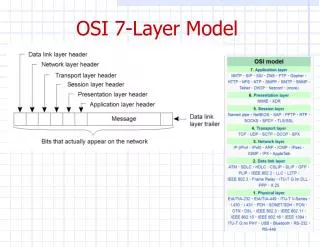
Encapsulation • Data exists at each layer contained within a unit called a Protocol Data Unit (PDU). • PDU’s are referred two ways: N-PDU, and by special names. • The process by which data moves between PDU types is called Encapsulation • PDU move through interfaces between layers using Service Access Points (SAP)
PDU’s And the OSI Model Encapsulation Decapsulation
Layer 1: The Physical Layer • Defines physical medium and interfaces • Determines how bits are represented • Controls transmission rate & bit synchronization • Controls transmission mode: simplex, half-duplex, & full duplex • PDU: Bits • Devices: hubs, cables, connectors, etc…
Layer 2: The Data Link Layer • PDU: Frames • Keeps Link alive & provides connection for upper layer protocols • Based on physical (flat) address space • Physical addresses are fixed and don’t change when the node is moved • Medium/media access control
The Data Link Layer (cont.) • Flow control and error detection/correction at the frame level. Think collisions… • Topology • Ex: Ethernet, Token Ring, ISDN • Sublayers: MAC (framing, addressing, & MAC) & LLC (logical link control – gives error control & flow control) • Devices: switches, bridges, NIC’s
Layer 3: The Network Layer • PDU: Packet • End to end delivery of packets • Creates logical paths • Path determination (routing) • Hides the lower layers making things hardware independent • Uses logical hierarchical addresses
The Network Layer (cont.) • Logical hierarchical addresses do change when a node is moved to a new subnet • Devices: routers, firewalls
Layer 4: The Transport Layer • PDU: Segment • Service Point Address (more often called a port) used to track multiple sessions between the same systems. SPA’s are used to allow a node to offer more than one service (i.e. it could offer both mail and web services) • This layer is why you have to specify TCP or UDP when dealing with TCP/IP
The Transport Layer (cont.) • Must reassemble segments into data using sequence numbers • Can use either connectionless or connection oriented sessions • Connectionless sessions rely on upper layer protocols for error control and are often used for faster less reliable links • Ex: UDP (used by things like NFS & DNS)
The Transport Layer (cont.) • Connection oriented sessions require the sender to first request a connection, the receiver to acknowledge the connection, and that they negotiate how much data can be sent/received before its reception is acknowledged • Uses acknowledgements & retransmission for error correction • Example: TCP (used by things like telnet, http)
Layer 5: The Session Layer • PDU: Data (from here on up) • Sometimes called the dialog controller, this layer establishes, maintains, and terminates sessions between applications • Sets duplex between applications • Defines checkpoints for acknowledgements during sessions between applications
The Session Layer (cont.) • Provides atomization – Multiple connections can be treated as one virtual session. If one fails or is terminated, all should be terminated. • Identifies raw data as either application data or session control information • Uses fields provided by layers 3 & 4 to track dialogs between applications / services • Provides translations for naming services • Ex: RPC, X-Windows, LDAP, NFS
Layer 6: The Presentation Layer • Data formatting, translation, encryption, and compression • Ex: ASCII, EBCDIC, HTML, JPEG
Layer 7: The Application Layer • Provides communication services to applications • Ex: HTTP, FTP, SMTP
Encapsulation Review Example of the encapsulation / decapsulation process
Address Resolution • Two problems: • #1 Layer 3 address resolution • #2 Layer 3 to Layer 2 resolution • IP vs IPX approaches
Larger Example • Scenario: sending a message between subnets. • Source and Destination Layer 3 addresses don’t change • Source and Destination Layer 2 addresses do • How are addresses resolved?
The Practical Benefits Of Understanding The OSI Model • Helps with packet analysis • Helps foresee problems • Aides in network design (especially on large scale networks)
Network Design & Admin Issues • Examining network protocols and how they relate to the OSI model help aide network administers design networks and help admins troubleshoot strange behavior. • If you don’t understand what mechanisms your network is using to communicate, you are more likely to introduce new problems while trying to fix old ones.
Example #1 • Admin wants to play around with DHCP so they put the machines that they want to use on “private IP addresses”. • What will happen to “normal” DHCP users?
Example #2 • Network congestion: Admin notices that he is seeing to much traffic on his network. He decides to break his network in two using a router. • What are some potential problems associated with this? • What might be some better solutions?
TCP/IP Model • Much older than OSI model • Consists of 4 layers instead of 7 • TCP/IP model can be mapped to the OSI model
IEEE Standards • IEEE project 802 started in 1985 • Adopted by ANSI in 1987 • Recognized as an international standard by the ISO as ISO 8802 • Deals with layers 1 & 2
IEEE Standards (cont.) • At the data link layer (layer 2), defines MAC and LLC sublayers • LLC covers media independent topics (802.2 is the LLC standard) • MAC topics are dependent on media (802.3, 802.11, 802.5) • At the physical layer (layer 1), defines a PMI and PMD