Download
1 / 21
330 likes | 816 Vues
FLOWMETER SELECTION. “Everything you forget to ask yourself before applying a flowmeter, that comes back to bite you in the rear later on.”. FLOWMETER SELECTION. NOT A “NO BRAINER” LESSER OF ALL EVILS MANY DIFFERENT TECHNOLOGIES TO CHOOSE FROM TIERED OFFERINGS WITHIN TECHNOLOGIES

E N D
FLOWMETER SELECTION “Everything you forget to ask yourself before applying a flowmeter, that comes back to bite you in the rear later on.”
FLOWMETER SELECTION NOT A “NO BRAINER” • LESSER OF ALL EVILS • MANY DIFFERENT TECHNOLOGIES TO CHOOSE FROM • TIERED OFFERINGS WITHIN TECHNOLOGIES • CONTROL SYSTEMS
WHY MEASURE THE FLOW? • PERMIT REPORTING REQUIREMENTS • HOW MUCH IS PRODUCED • HOW MUCH IS CONSUMED • BLENDING: CONTINUOUS OR BATCH • CUSTODY TRANSFER BETWEEN UTILITIES • MONITOR / INDICATE
VARIOUS FLOWMETER TYPES HEAD PRODUCING (DP) - ORIFICE - NOZZLE - VENTURI - WEDGE - ANNUBAR / PITOT TUBE - ELBOW TAP - TARGET - VARIABLE AREA / ROTAMETER - VENTURI CONE POSITIVE DISPLACEMENT - DIAPHRAGM SEAL - MECHANICAL SEAL VELOCITY - TURBINE - ELECTROMAGNETIC - VORTEX - ULTRASONIC - SONAR DIRECT MASS - CORIOLIS - THERMAL INFERED MASS - MULTI-VARIABLE DP
FLOWMETER SELECTION FACTORS * FLUID PROPERTIES LIQUID OR GAS TEMPERATURE AND PRESSURE DENSITY OR S.G. VISCOSITY LUBRICITY CHEMICAL MAKEUP ABRASIVENESS MULTIPLE PHASES SOLIDS CONTENT
FLOWMETER SELECTION FACTORS * INSTALLATION CONSIDERATIONS ORIENTATION FLOW DIRECTION UPSTREAM AND DOWNSTREAM ELEMENTS SERVICE ACCESS VIBRATION ELECTRICAL CLASSIFICATION RFI AND EMI CAVITATION INTERMITTENT / PULSATING FLOW SIZE / WEIGHT
FLOWMETER SELECTION FACTORS * PERFORMANCE CONSIDERATIONS ACCURACY REPEATABILITY LINEARITY HYSTERESIS RANGEABILITY / TURNDOWN UPDATE RATE DEAD TIME RESPONSE TIME STABILITY / FILTER CAPABILITY TOTAL PROBABLE ERROR
FLOWMETER SELECTION FACTORS * ENVIRONMENTAL CONSIDERATIONS AMBIENT TEMPERATURE EFFECTS BAROMETRIC PRESSURE EFFECTS FUGITIVE EMISSIONS POTENTIAL HUMIDITY EFFECTS SAFETY FACTORS SUBMERGENCE POTENTIAL LIGHTNING PROTECTION AREA CLASSIFICATION
FLOWMETER SELECTION FACTORS * ECONOMIC CONSIDERATIONS PURCHASE PRICE INSTALLATION COSTS OPERATING COSTS CALIBRATION COSTS MAINTENANCE COSTS INSTRUMENT LIFE RELIABILITY SPARES COST AND AVAILABILITY PUMPING COST FROM HEADLOSS PROCESS / PLANT OPTIMIZATION
FLUID PROPERTIES PERFORMANCE INSTALLATION ECONOMIC FACTORS APPLICATION CONTROL MONITOR INDICATE CUSTODY TRANSFER LIQUID, GAS, STEAM CONDUCTIVITY MULTI-PHASE VISCOSITY PRESSURE TEMPERATURE ACCURACY REPEATABILITY TEMPERATURE EFFECT LINE SIZE VIBRATION PIPE RUNS SUBMERGENCE COST INSTALLATION RELIABILITY ENVIRONMENTAL & SAFETY METER SELECTED TO VENDORS EMMISSIONS HAZARDOUS WASTE DISPOSAL LEAK POTENTIAL SHUT DOWN SYSTEM? CORIOLIS DP MAGMETER VORTEX FLOWMETER SELECTION PROCESS
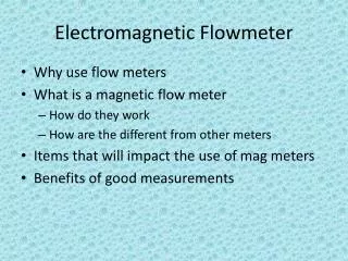
Variable Flow Rate (ft/s) SST Tube Conductive Process Medium Flange Faraday’s Law: E=kBDV k=Proportionality constant B=Magnetic field strength D=Length of conductor V=Velocity of conductor E=Induced voltage (linear with velocity) Lining Field Coils “E” Sensing Electrodes “E” MAG METER BASICS Theory of Operation
MAGNETIC FLOWMETER BASICS PROS AND CONS PROS CONS TRUE VOLUME INITIAL COST (AC) ACCURACY CONDUCTIVITY WIDE RANGEABILITY MATERIAL COMPATIBILITY LOW FLOW CAPABILITY NUMBER OF DESIGNS ZERO HEAD LOSS VELOCITY LIMITS BI-DIRECTIONAL/OBSTRUCTIONLESS INSENSITIVITY TO UPSTREAM PIPING
MAGNETIC FLOWMETER BASICS ACCURACY: +/- 0.2% TO 1% RANGEABILITY: 10:1 TO 50:1 REYNOLDS NUMBER: NO LIMIT PIPING EFFECTS: MINIMAL COST OF OWNERSHIP: INITIAL: L/H INSTALLATION: L/M OPERATION: M MAINTENANCE: L/M
Less Than Ideal Straight Run Installation Testing
Introduction • Standard specification for straight run piping to maintain specified accuracy • 5 pipe diameters upstream • 2 pipe diameters downstream • Distance measured from electrodes (center of the flowtube) • What if this requirement is not met?
Test Results Summary • Readings were offset by 0 to 3% • Offset could be positive or negative • Flow readings were repeatable to within 0.1% • Reading offset was dependent on the type of disturbance, length of upstream straight run, line size, and position of electrodes • Reading offset was independent of flow rate (velocity) within lab accuracy
Short Run Test Setup Weigh Tank TestMagmeter ReferenceMagmeter Upstream Dimensions Upstream Disturbance • Summary of Tests: • ½, 4, 10 and 24-inch meters • 4 inch test had extended scope, other line sizes had limited scope
Rosemount Magmeter4-inch Test Scope Test Magmeter Weigh Tank ReferenceMagmeter • Upstream Dimensions: • 0D • 1D • 2D • 3D • Upstream Disturbance: • Single Short-radius Elbow • Double Short Radius Elbow Out of plane • Double Short Radius Elbow In plane • 6 x 4 inch Reducer • Gate Valve in 3 positions • Butterfly valve in 3 positions • Summary of Tests: • 6 points per run (average is recorded) • 6 velocities from about ½ to 25 ft/s
4-inch: Single Elbow Setup • Piping schematic for the 4-inch single elbow test • Reference meter installed with more than 5D up and 2D down • Adjustable pipe sections used to test various lengths of upstream straight run Adjusted for different upstream lengths Similar piping schematics were used for the other disturbances and line sizes tested
Overall Summary • Best practice for magmeter installations is to have straight run of 5 pipe diameters upstream and 2 pipe diameters downstream • Less than ideal straight run will cause an offset or shift in the reading • Reading will still be repeatable • Reading offset is dependent on type of upstream disturbance, length of upstream straight run, line size, and position of electrodes, but independent of velocity • Correction factor could be entered electronically to accommodate the shift in reading