Download
1 / 24
780 likes | 3.22k Vues
Lecture 8 Power Amplifier (Class A). Induction of Power Amplifier Power and Efficiency Amplifier Classification Basic Class A Amplifier Transformer Coupled Class A Amplifier. Introduction.

E N D
Lecture 8 Power Amplifier (Class A) • Induction of Power Amplifier • Power and Efficiency • Amplifier Classification • Basic Class A Amplifier • Transformer Coupled Class A Amplifier EE3110 Power Amplifier (Class A)
Introduction • Power amplifiers are used to deliver a relatively high amount of power, usually to a low resistance load. • Typical load values range from 300W (for transmission antennas) to 8W (for audio speaker). • Although these load values do not cover every possibility, they do illustrate the fact that power amplifiers usually drive low-resistance loads. • Typical output power rating of a power amplifier will be 1W or higher. • Ideal power amplifier will deliver 100% of the power it draws from the supply to load. In practice, this can never occur. • The reason for this is the fact that the components in the amplifier will all dissipate some of the power that is being drawn form the supply. EE3110 Power Amplifier (Class A)
Amplifier Power Dissipation The total amount of power being dissipated by the amplifier, Ptot , is Ptot = P1 + P2 + PC + PT + PE The difference between this total value and the total power being drawn from the supply is the power that actually goes to the load – i.e. output power. Amplifier Efficiency h EE3110 Power Amplifier (Class A)
Amplifier Efficiency h • A figure of merit for the power amplifier is its efficiency, h . • Efficiency ( h ) of an amplifier is defined as the ratio of ac output power (power delivered to load) to dc input power . • By formula : • As we will see, certain amplifier configurations have much higher efficiency ratings than others. • This is primary consideration when deciding which type of power amplifier to use for a specific application. • Amplifier Classifications EE3110 Power Amplifier (Class A)
Amplifier Classifications • Power amplifiers are classified according to the percent of time that collector current is nonzero. • The amount the output signal varies over one cycle of operation for a full cycle of input signal. EE3110 Power Amplifier (Class A)
Efficiency Ratings • The maximum theoretical efficiency ratings of class-A, B, and C amplifiers are: EE3110 Power Amplifier (Class A)
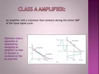
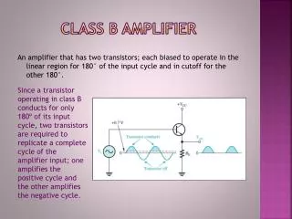
Class A Amplifier • output waveform same shapeinputwaveform + phase shift. • The collector current is nonzero 100% of the time. inefficient, since even with zero input signal, ICQ is nonzero (i.e. transistor dissipates power in the rest, or quiescent, condition) EE3110 Power Amplifier (Class A)
Basic Operation Common-emitter (voltage-divider) configuration (RC-coupled amplifier) EE3110 Power Amplifier (Class A)
Typical Characteristic Curves for Class-A Operation EE3110 Power Amplifier (Class A)
Typical Characteristic • Previous figure shows an example of a sinusoidal input and the resulting collector current at the output. • The current, ICQ , is usually set to be in the center of the ac load line. Why? (DC and AC analyses discussed in previous sessions) EE3110 Power Amplifier (Class A)
DC Input Power The total dc power, Pi(dc) , that an amplifier draws from the power supply : Note that this equation is valid for most amplifier power analyses. We can rewrite for the above equation for the ideal amplifier as EE3110 Power Amplifier (Class A)
AC Output Power AC output (or load) power, Po(ac) Above equations can be used to calculate the maximum possible value of ac load power. HOW?? Disadvantage of using class-A amplifiers is the fact that their efficiency ratings are so low, max 25% . Why?? A majority of the power that is drawn from the supply by a class-A amplifier is used up by the amplifier itself. Class-B Amplifier EE3110 Power Amplifier (Class A)
Limitation EE3110 Power Amplifier (Class A)
Example Calculate the input power [Pi(dc)], output power [Po(ac)], and efficiency [h] of the amplifier circuit for an input voltage that results in a base current of 10mA peak. EE3110 Power Amplifier (Class A)
Transformer-Coupled Class-A Amplifier A transformer-coupled class-A amplifier uses a transformer to couple the output signal from the amplifier to the load. The relationship between the primary and secondary values of voltage, current and impedance are summarized as: N1, N2 = the number of turns in the primary and secondary V1, V2 = the primary and secondary voltages I1, I2 = the primary and secondary currents Z1, Z2 = the primary and seconadary impedance ( Z2 = RL ) EE3110 Power Amplifier (Class A)
Transformer-Coupled Class-A Amplifier • An important characteristic of the transformer is the ability to produce a counter emf, or kick emf. • When an inductor experiences a rapid change in supply voltage, it will produce a voltage with a polarity that is opposite to the original voltage polarity. • The counter emf is caused by the electromagnetic field that surrounds the inductor. EE3110 Power Amplifier (Class A)
Counter emf This counter emf will be present only for an instant. As the field collapses into the inductor the voltage decreases in value until it eventually reaches 0V. EE3110 Power Amplifier (Class A)
DC Operating Characteristics The dc biasing of a transformer-coupled class-A amplifier is very similar to any other class-A amplifier with one important exception : the value of VCEQ is designed to be as close as possible to VCC. The dc load line is very close to being a vertical line indicating that VCEQ will be approximately equal to VCC for all the values of IC. The nearly vertical load line of the transformer-coupled amplifier is caused by the extremelylow dc resistance of the transformer primary. VCEQ = VCC – ICQ(RC + RE) The value of RL is ignored in the dc analysis of the transformer-coupled class-A amplifier. The reason for this is the fact that transformer provides dc isolation between the primary and secondary. Since the load resistance is in the secondary of the transformer it dose not affect the dc analysis of the primary circuitry. EE3110 Power Amplifier (Class A)
AC Operating Characteristics • 1. Determine the maximum possible change in VCE • Since VCE cannot change by an amount greater than (VCEQ – 0V), vce = VCEQ. • 2.Determine the corresponding change in IC • Find the value of Z1 for the transformer: Z1 = (N1/N2)2Z2 and ic = vce / Z1 • 3. Plot a line that passes through the Q-point and the value of IC(max). • IC(max) = ICQ + ic • 4. Locate the two points where the load line passes through the lies representing the minimum and maximum values of IB. These two points are then used to find the maximum and minimum values of IC and VCE EE3110 Power Amplifier (Class A)
The Power Supply for the amplifier : PS = VCCICC Maximum peak-to-peak voltage across the primary of the transformer is approximately equal to the difference between the values of VCE(max) and VCE(min) : VPP = VCE(max) – VCE(min) Maximum possible peak-to-peak load voltage is found by V(P-P)max = (N2 / N1)V PP The actual efficiency rating of a transformer-coupled class-A amplifier will generally be less than 40%. Maximum load power and efficiency EE3110 Power Amplifier (Class A)
There are several reasons for the difference between the practical and theoretical efficiency ratings for the amplifier : • The derivation of the = 50% value assumes that VCEQ = VCC . In practice, VCEQ will always be some value that is less the VCC . • The transformer is subject to various power losses. Among these losses are couple loss and hysteresis loss. These transformer power losses are not considered in the derivation of the = 50% value. EE3110 Power Amplifier (Class A)
One of the primary advantages of using the transformer-coupled class-A amplifier is the increased efficiency over the RC-coupled class-A circuit. • Another advantage is the fact that the transformer-coupled amplifier is easily converted into a type of amplifier that is used extensively in communications :- the tuned amplifier. • A tuned amplifier is a circuit that is designed to have a specific value of power gain over a specific range of frequency. EE3110 Power Amplifier (Class A)