Dogleg Beam-loading Experiment
Dogleg Beam-loading Experiment. Status and plans. J.L. Navarro (CERN), for the Dogleg Team. Workshop, 3 – 7 February 2014. Outline. What are we studying in dogleg and Why? The Dogleg experiment layout Current status…: Phase I and results …and plans: Phase II Summary. Where…?.


Dogleg Beam-loading Experiment
E N D
Presentation Transcript
Dogleg Beam-loading Experiment Status and plans J.L. Navarro (CERN), for the Dogleg Team Workshop, 3 – 7 February 2014
Outline • What are we studying in dogleg and Why? • The Dogleg experiment layout • Current status…: Phase I and results • …and plans: Phase II • Summary
Where…? • The study is focused on the accelerating structures of the Main Beam Linac • Traveling waves cavities • Nominal gradient ~ 100 MV/m • Nominal RF pulse length ~ 240 ns (160 ns flat top) • Peak Power ~ 61 MW • Max. Surf. Field ~ 230MV/m
What and Why? Strong Accelerating fields (~100 MV/m) Problem of Break Downs (BD): Very fast (10 ns – 100 ns) and localized dissipation of stored energy in the structure. • Undesired effects: • Loss of acceleration • Damage in the structure • Kick in the beam • … T24 TD18 T18 TD24 TD24r05 TD26CC • Luminosity Reduction: • Max DB rate allow for CLIC specifications: • 3 10-7 BD pulse-1 m-1 Log(BDR) 1/pulse/m Unloaded Accelerating Gradient MV/m
Beam loading effect Beam Loading modifies the gradient distribution along the structure Unloaded Current increase Loaded CLIC nominal BD never studied in loaded structures Unloaded
The Dogleg experiment Main goal: Measure and comparison (unloaded vs loaded) of the BD rate in a T24 structure Tapered linearly Not Damped 2 coupling cells + 24 cells CERN’s T24 (12WNDSvg1.8 KEK N1) Inner volume Thanks to A. Grudiev for HFSS model • Two phases experiment: • Beam only: • Optic design • Hardware installation • Beam commissioning • RF + Beam (middle 2014): • RF commissioning • Structure conditioning • RF + beam studies Done
Experiment layout • Experiment located in the Dogleg Line of the CTF3 Linac (old PETS Line) • Beam side: • CTF3 Drive Beam modified to mimic CLIC main beam • Pulse compression to reach ~125 MeV at structure • Nominal current of ~1.2 A • Pulse length up to 250 ns • RF side: • 90 MW RF power delivered by XBox1 • 35 Meters of low loss waveguide • 60 MW RF power at the structure • Instrumentation side: • Fixed 6mm collimator to protect the structure • BPM upstream and downstream • Movable slit to clean up beam Dogleg XBox1 Movable slit Upstream BPM Collimator Structure Downstream BPM
RF wave guide installation S21 Reconstructed (Xiaowei Wu) Overall waveguide efficiency ~ 67% 0.87 0.8 Xbox1 wall CTF2 CTF3 • The round group delay time is 230 ns (~35 m). • To provide nominal CLIC RF pulse, XBOX1 klystrons needs to deliver 36 MW x 1.5s
Optics design Objective: Transport the beam trough the Linac up to the structure requiring… - Full transmission efficiency - Minimum beam size on average inside the structure Maximize relative distances between aperture and beam size (M. Dayyani). MAD model by F. Tecker. Structure Beam envelope Structure Re-matched optics for last running Linac+dogleg
Data Acquisition System: Phase I SIS 3320 250MHz 12bit ADC • Online Software monitoring: • Produced power from the beam • Reflected power (Break-down) • BPMs current (looses) • Online BD detection
Phase I Results: Running of May 2013 Upstream and downs stream BPMs ~ 90% transmission with no nominal optics Horizontal orbit very offset Limited by broken movable slit S CP.QDC 0120 CP.VPI 0125 CP.BHC 0105 CP.BPM 0115 CP.QFC 0110 CP.SLH 0107 CP.BHC 0145 CP.QFC 0130 No transmission with nominal optics due to big steering induced in the quads. Broken slit
Phase I Results: Running of May 2013 70 mV Raw signal from OASIS Two different pulses length at ~1.3 A… Output transmitted channel Input reflected channel ~9 MW … and some break down
Phase I Results: Running of May 2013 • Theoretical prediction • BPM 240 current (before structure) • BPM 280 current (after structure) Upstream BPM shows the correct tendency with a systematic error in power It suggest loses at the very end or after the structure.
Phase I Results: Running of May 2013 • Theoretical prediction • BPM 240 current (before structure) • BPM 280 current (after structure) 3.3 dB error in upstream BPM 2.4 dB error in downstream BPM
Phase I Results: Running of May 2013 Measured power scaled down by 3dB. Shape reproduced… …but error in calibration
Phase I Results: Running of May 2013 • Summary of first run: • No transmission with nominal optics • 90% with experimental optics • First RF beam induced signals and break downs observed • ~ 3dB of error in calibration • Theoretical pulse shape reproduced • Movable slit broken • During summer shutdown: • The slit was repaired (mechanical parts and cabling) • The surveyors measured components alignment (more than 1.5 mm for some quads) • The acquisition system was recalibrated using TWT (Thanks to L. Timeo, S.F. Rey) Thanks to S. Doebert, F. Tecker and T. Wisznowskifor a great job when repairing the slit by ourselves.
Phase I Results: Running of Dec 2013 We reach ~ 80% of transmission with almost the nominal optics (only one quad lowered) As expected some quads introduce steering and needs to be realigned (done during Christmas shutdown.) Dispersion is closed and we have some margin to improve transmission
Phase I Results: Running of Dec 2013 And from the RF side: • Theoretical prediction • BPM 240 current (before structure) • BPM 280 current (after structure) Theoretical model fits within experimental uncertainties Data from May 2013 Data from Dec 2013 (after DAQ recalibration)
Dogleg Beam-loading Experiment Status… • Two phases experiment: • Beam only: • Optic design • Hardware installation • Beam commissioning • RF + Beam (middle 2014): • RF commissioning • Structure conditioning • RF + beam studies • Phase I summary: • Technical problems with slit solved • Successful calibration • RF waveguide installed with overall RF efficiency of 67%. • Acceptable (80%) transmission with nominal optics (better after realignment) • Realignment of components done during Christmas shutdown … and prospects. Phase II approaching!!
Tentative Planning • Xbox will be connected in the next weeks • Some time for synchronization, calibration, conditioning… • Specific slot reserved for dogleg during summer restarting. Ready for and exciting dogleg 2014 campaign!
TE-VCS XBOX CTF3 RF/PM M. Filippova D. Gudkov P. Guyard S. Lebet A. Olyunin G. Riddone A. Samochkine I. Syratchev A. Solodko P. De Souza • E. Paju M. Dayyani S. Doebert J.L. Navarro S.F. Rey F. Tecker L. Timeo T. Wisznowski All operators S. Curt A. Degiovanni G. McMonagle J. Tagg B. Woolley X. Wu Thanks for your attention Special thanks to A. Grudiev for very useful discussions and material.
New VISTAR By D. Gamba Thanks for your attention
Backup Accelerating gradients achieved in tests. Status: 4-9-2012 loaded
Backup (I. Syrachev. CLIC Workshop 2013) Structure under test: CERN’s T24 (12WNDSvg1.8 KEK N1) No damping
Calibration (I. Syrachev. CLIC Workshop 2013) -49.32 -52.04 Insertion losses of the input/output waveguide network (splitter and bends) is -0.15 dB (=0.967)
Phase I Results: Running of Dec 2013 And from the RF side: Theoretical model fits within experimental uncertainties Data from May 2013 P[MW]=2.62 I2 P[MW]=3.17 I2 P[MW]=1.91 I2 Data from Dec 2013 (after DAQ recalibration)
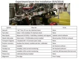
Dog-leg waveguide line installation status. • All the components are installed. • Connected to accelerated structure and closed for vacuum. • Vacuum leaks checked (tight). Ready to be connected to XBOX1.
RF power transmission measurements S11 data Transmission (simulated) S21 Reconstructed (Xiaowei Wu) Short circuit(+offset) Reflection Matched load • The measured RF power transmission efficiency is 80%. • Reflection is below -27dB. • The group delay time is 75 ns (~23.5 m).
Overall power transmission efficiency 0.87 0.8 Xbox1 wall CTF2 CTF3 • The overall measured RF power transmission efficiency is 67%. • The round group delay time is 230 ns (~35 m). • To provide nominal CLIC RF pulse, XBOX1 klystrons needs to deliver 36 MW x 1.5s