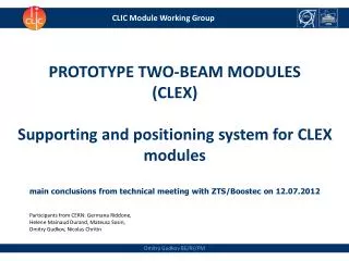
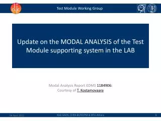
Modal Analysis of Test Module Supporting System: Report and Updates
This report provides an update on the modal analysis of the test module supporting system in the lab. The goal is to analyze the modal behavior of different configurations such as girders, V-shaped supports, and cradles, and identify eigenfrequencies. Accelerometers were used to measure vibrations and a spectrum analyzer to interpret data. Results show confirmation of simulated modal shapes and recommendations for optimizing system stability. Future tasks include further modal analysis of different sub-assemblies. Comments and feedback are appreciated.

Modal Analysis of Test Module Supporting System: Report and Updates
E N D
Presentation Transcript
Test Module Working Group Update on the MODAL ANALYSIS of the Test Module supporting system in the LAB Modal Analysis Report EDMS 1184906: Courtesy of T. Kostamovaara
Strategy • Modal measurements for the supporting system of the Test Modules in the LAB: • GOAL: To analyze the modal behaviour of the different configurations of the supporting system (girders, V-shaped supports and cradles) and identify the existing eigenfrequencies of the supporting system sub-assemblies. • Sub-assemblies: • DB V-shaped supports; • MB V-shaped supports; • DB girder with integrated V-shaped supports and cradles assembled, • MB girder with integrated V-shaped supports and cradles assembled. • Methodology: • Accelerometers glued on the supporting components; • Excitation force ( < 50 N) imposed with a special impact hammer (plastic-end tip); • Signal received by the accelerometers and the impact hammer tip and then transmitted to a spectrum analyzer; • Dedicated software interprets and analyses the measurements. • Comparison of: • Preliminary simulation values/modes (EDMS doc : 1083833); • Simulation values/modes (EDMS doc :1098928); • Modal measurements/modes (EDMS doc : 1159189), • Modal measurements/modes (EDMS doc : 1184906).
Testing Configuration Courtesy of T. Kostamovaara Excitation method Accelerometers • The accelerometers were assembled on key positions for the modal measurements so as to identify the modal behaviour or the supporting system components (V-shaped supports, girder, cradles, etc.). Such key points are the 1, 6, 10, 15 and 20 of the figure. DB T-0 (LAB) Girder (Boostec)
Results Courtesy of T. Kostamovaara Rigid body mode: 8 Hz Rigid body mode: 15 Hz Rigid body mode: 19 Hz Rigid body mode: 37 Hz 1st simulated (bending) mode: 50 Hz 2nd mode: 141 Hz 1st (bending) mode: 59 Hz *RIGID BODY MODE: The distance between any two given points of a rigid body remains constant in time regardless of external forces exerted on it.
Results – Conclusions Courtesy of T. Kostamovaara • The simulated 1st and 2nd modal shapes are confirmed by the measurements. • Rigid body modes measured in between 0-50 Hz: Resonance ~50 Hz with smaller damping needs to be avoided. • The alignment plates under the cradles can generate a series of body modes. • Stability could be optimized by rigidifying the alignment plates (e.g. cast them in cement). • Increase the frequency of the 1st bending mode (if needed) by dedicated design optimization of the girder cross section.
Summary and Future steps • Summary of accomplished tasks: • Modal simulation for the Main Beam and the Drive Beam configurations of the LAB; • Modal analysis for the Main Beam and Drive Beam V-shaped supports; • Modal analysis of the sub-assembly of the Drive Beam girder, V-shaped supports and cradles. • Future tasks: • Modal analysis of the sub-assembly of the Main Beam girder, V-shaped supports and cradles; Comments are always welcome!