Download
1 / 1
10 likes | 140 Vues
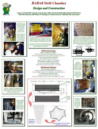
Overhead view of clean room showing parallel operation of two stringing teams, each with two human operators and a transport robot Operators thread wire on needles for robot transport, receive needle at far end, and fasten wire by crimping.

E N D
Overhead view of clean room showing parallel operation of two stringing teams, each with two human operators and a transport robot Operators thread wire on needles for robot transport, receive needle at far end, and fasten wire by crimping Close-up of rear endplate after completion of 5 superlayers (above) showing dense pattern of plastic and metal feedthroughs and crimp pin for holding wire. Typical cell shown in cross section below. Sense wires are at 1960V, requiring 6mm-diameter plastic insulator for feedthrough. Field wires are at ground potential. Partially installed wire field, showing one of two industrial robots used to transport wire between endplates. With no human traffic, inner clean room between endplates maintained below class 1000. The pattern of reflections in the photographs occur due to the superlayer pattern with wires having the same small-angle stereo direction. After the completion of stringing, a small number of wires was replaced with chamber swung to vertical position Outer cylinder installed in two halves and load transferred from fixtures Assembly of endplates in stringing fixtures. Deflection studies under simulated full load (above) and spider structure for holding wire load during stringing (below) Installation of the chamber into BABAR as seen from the forward (right) and rear ends of the detector (below) Precision drilling of feedthrough holes achieved 25mm RMS position accuracy, as determined by quality assurance measurements BABAR Drift Chamber Design and Construction Annecy, Carleton/CRPP, Colorado, Colorado State, LBNL, Maryland, McGill, MIT, Montreal, INFN Padova, INFN Pisa, Princeton, INFN Rome, UC San Diego, UC Santa Cruz, SLAC, TRIUMF, UBC, and Victoria 24mm Al Endplate 12mm Al Endplate Drift System Design 40-layer small-cell chamber 7104 drift cells formed from hexagonal field wire pattern 80 & 120 mm Aluminum field wires and 20 mm tungsten sense wires Layers organized into superlayers Wire directions in axial-u-v pattern Allows fast Level 1 trigger based on segments 80:20 helium:isobutane gas mixture Low-mass gas to minimize multiple scattering Small Lorentz angle results in simple t-to-d relation Mechanical Structure Thin aluminum endplates 30K precision holes locate feedthroughs with crimp pins Forward endplate reduced to 12 mm thickness in acceptance region Load-bearing cylindrical walls 1-mm thick beryllium inner wall (40% load) Nomex-carbon fiber composite outer wall assembled in two halves Beryllium inner wall Thin Al forward endplate Superlayer grouping of drift layers Typical Drift Cell (1.2x1.8cm) with 50 ns isochrones