Cell-Coupled Drift Tube Linac
260 likes | 442 Vues
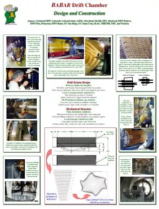
Cell-Coupled Drift Tube Linac. M. Pasini, CERN AB-RF. Contents. CCDTL concept and design Beam parameters Layout Test and measurements of the CERN pre-prototype Test and measurements of the ISTC prototype Summary. • • •. bl. bl. bl. bl. 3/2 bl. CCDTL concept and design.

Cell-Coupled Drift Tube Linac
E N D
Presentation Transcript
Cell-Coupled Drift Tube Linac M. Pasini, CERN AB-RF LINAC4 Machine Advisory Committee 1st meeting CERN January 29-30, 2008
Contents • CCDTL concept and design • Beam parameters • Layout • Test and measurements of the CERN pre-prototype • Test and measurements of the ISTC prototype • Summary LINAC4 Machine Advisory Committee 1st meeting CERN January 29-30, 2008
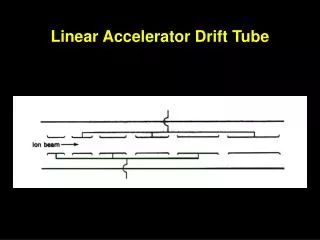
• • • bl bl bl bl 3/2 bl CCDTL concept and design • CCDTL = Cell Coupled Drift Tube Linac • Accelerating gap and Drift Tubes do not change within the single tank • Quads are placed between the tanks not inside the DTs • Intertank spacing is constant (250 mm) The resonating mode is π/2 250 mm LINAC4 Machine Advisory Committee 1st meeting CERN January 29-30, 2008
CCDTL mechanical design (1/2) LINAC4 Machine Advisory Committee 1st meeting CERN January 29-30, 2008
CCDTL mechanical design (2/2) • Each accelerating tank is split in two halves • The CCDTL half-tanks are made out of copper-plated stainless steel, with cooling channels directly machined in the external part of the tank cylinder • Each half-tank contains a drift tube made in copper and cooled via the supporting stem • Vacuum seals and RF joints between half tanks and coupling cell are provided by “Helicoflex” type of gasket LINAC4 Machine Advisory Committee 1st meeting CERN January 29-30, 2008
Mechanical details LINAC4 Machine Advisory Committee 1st meeting CERN January 29-30, 2008
Beam Parameters LINAC4 Machine Advisory Committee 1st meeting CERN January 29-30, 2008
CCDTL layout CCDTL module LINAC4 Machine Advisory Committee 1st meeting CERN January 29-30, 2008
CCDTL Layout 50-102.5 MeV LINAC4 Machine Advisory Committee 1st meeting CERN January 29-30, 2008
Geometry details LINAC4 Machine Advisory Committee 1st meeting CERN January 29-30, 2008
Coupling factors – field stability • Measured coupling factors from the prototypes at low energy (40 MeV) k = 0.89% (simulated was 0.88%) • Simulated coupling factors at high beta (100 MeV) k = 0.52% 50 kHz tuning error in 5 resonating cell LINAC4 Machine Advisory Committee 1st meeting CERN January 29-30, 2008
Tuning requirements • 1 fixed tuner per half tank and 2 per coupling cell • 1 moving tuner at low energy to compensate for temperature drift • 2 moving tuners at high energy to compensate for temperature drift ∆T of 10 degrees should give a frequency variation of about 40 kHz (estimate) LINAC4 Machine Advisory Committee 1st meeting CERN January 29-30, 2008
CERN pre-prototype LINAC4 Machine Advisory Committee 1st meeting CERN January 29-30, 2008
Measurements results Q0=27281 which is 79% of Superfish (the plating is only in one half of the Helicoflex joint groove) LINAC4 Machine Advisory Committee 1st meeting CERN January 29-30, 2008
Spectrum Measurements LINAC4 Machine Advisory Committee 1st meeting CERN January 29-30, 2008
High power test area LINAC4 Machine Advisory Committee 1st meeting CERN January 29-30, 2008
High Power Measurements • Started with vacuum level of 10-8 mbar • Conditioning lasted less then 2 days • Max field achieved is 34.2 MV/m on the drift tube • Kp = 1.72 • E0 = 4 MV/m • The temperature on the cavity was monitored: at 0.1% duty cycle the temperature was stabilized at around 30 deg with a minimum of 5 l/min water flow only in the drift tube. 7 kHz shift was observed in the resonance frequency • At SPL duty cycle temperature reached 58, 76 and 80 degrees in the drift tube holder, coupling iris and plunger tuner. In particular the temperature rise in the coupling iris is due to the over-coupled matching between waveguide and cavity; the resonant frequency decreased by 128 kHz from cold to hot condition. LINAC4 Machine Advisory Committee 1st meeting CERN January 29-30, 2008
Status of the ISTC prototype RFNC-VNIITF, Snezhinsk BINP, Novosibirsk LINAC4 Machine Advisory Committee 1st meeting CERN January 29-30, 2008
Comparison of the field profile measurements done at CERN and at BINP (green) Measurements results LINAC4 Machine Advisory Committee 1st meeting CERN January 29-30, 2008
Alignment checks Alignment shaft Alignment flange 2 LINAC4 Machine Advisory Committee 1st meeting CERN January 29-30, 2008
Waveguide coupling measurements LINAC4 Machine Advisory Committee 1st meeting CERN January 29-30, 2008
Installation in the bunker and final tuning • Frequency: 0-mode 350.974 MHz • π/2-mode 352.060 MHz • π-mode 353.219 MHz • k = 0.9% • The frequency change of the π/2-mode after vacuum was +84 kHz. • Q0=36700 which is 84% of Superfish value. LINAC4 Machine Advisory Committee 1st meeting CERN January 29-30, 2008
High power measurements • Conditioning of the cavity lasted about 1 week. (An increased pumping capacity with an automatic conditioning routine will probably decrease the time for conditioning) • After the conditioning we could easily put power inside the cavity in excess of 330kW at both Linac4 duty cycle (0.1%) and SPL duty cycle (5%). Nominal gradient requires 310 kW. • The power was limited by the high voltage power supply (60kV instead of 100kV) • The temperature on the cavity was monitored: at 5% duty cycle the temperature on the external part of the drift tube raised by 40 degrees, while tuners in the accelerating cells went up to 100 deg. C. The resonant frequency decreased about 80 kHz. LINAC4 Machine Advisory Committee 1st meeting CERN January 29-30, 2008
Summary • A new layout of the CCDTL has been optimized • Test and measurements of the CERN pre-prototype and ISTC prototype are completed. The cavities didn’t show any limitation in reaching the nominal field and beyond. • For the LINAC4 duty cycle a limited amount of cooling water (~5l/m) is required for the drift tubes • For the SPL duty cycle additional cooling must be added in the tuners LINAC4 Machine Advisory Committee 1st meeting CERN January 29-30, 2008