Download
1 / 34
370 likes | 638 Vues
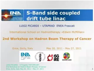
S-Band side coupled drift tube linac. LUIGI PICARDI – UTAPRAD ENEA Frascati International School on Hadrontherapy «Edwin McMillan» 2nd Workshop on Hadron Beam Therapy of Cancer Erice, Sicily, Italy May 20, 2011 - May 27, 2011. Just an introduction.

E N D
S-Band side coupled drift tube linac LUIGI PICARDI – UTAPRAD ENEA Frascati International School on Hadrontherapy «Edwin McMillan» 2nd Workshop on Hadron Beam Therapy of Cancer Erice, Sicily, Italy May 20, 2011 - May 27, 2011
Just an introduction The ENEA Accelerator Laboratory is in ENEA Frascati Research Centre. It grew up as an extension of the accelerator group that built in the fifties the 1 GeV Frascati Electrosynchrotron, and is indeed housed just in the same old building. Today it is a part of “Application of Radiation” Technical Unit UT APRAD
Small electron accelerators In late sixties the competences in accelerator physics in Frascati area were split between INFN and CNEN (now ENEA) , two big scientific institutions, and after the synchrotron shut down in 1974, some of them who still stayed in CNEN were addressed to the development of accelerator for applications in medical and industrial fields. Working together with other laboratories in ENEA Casaccia which have expertise in Radiobiology and Radiation Metrology and with other italian scientific institutions like National Institute of Health (ISS), INFN, and research Hospitals and Universities, the knowhow in the accelerator field was transferred in the years ‘80 – ’90 to an Italian company named HITESYS with the site in Aprilia close to Rome. The company was then able to built a Intra Operative Radiation Therapy (IORT) accelerator named NOVAC7 (the first machine installed in an hospital in 1997)
IORT: IntraOperative Radiation Therapy In 2001 the company Hitesys split in two companies NRT company in Aprilia that now is produced Novac 7, SORDINA in north Italy close Treviso which produces the LIAC accelerator, similar to the NOVAC More than 40 machines NOVAC7 and LIAC, are running in hospitals in Italy, Europe, and recently USA and in other countries. ENEA is always ready to promote new developments. NOVAC7 LIAC (NRT) (Sordina)
ENEA Accelerator Lab on Protontherapy In 1993 ENEA joins the Hadrontherapy Collaboration setup by Ugo Amaldi in 1991. From the beginning the problem of veryhuge and costlyhadrontherapyfacilitieswasunderlined. The comparisonbetween the performance-raising X-rays radiotherapy to the nevertheless excellent protontherapywasimmediatelyevident. Protontherapy, and more, hadrontherapy shows high plant costs, and a very late mortage . ENEA coordinated therefore a study on the development of compact accelerators in which two compact synchrotrons, a SC cyclotron and a 3 GHz linear accelerator were studied and compared.
Coupling Cavity PMQ Accelerating Tank RF input ENEA Accelerator Lab on Protontherapy In particular, in 1994-95 ENEA proposed the development of a 3 GHz linear accelerator studied in collaboration with CERN and INFN that focused the attention on the development of al linear machine as an alternative to circular machines. The main difference with a similar proposal by Hamm et al., in 1991 was in the segment 7 – 70 MeV where, instead of a 425 MHz DTL, a 2.998 GHz new structure, called SCDTL, was foreseen. ENEA patented this structure in Europe in 1995
ENEA Accelerator Lab on Protontherapy The ENEA linear accelerator proposal had the characteristic that only a small part, the low energy injector was at a frequency different from 3 GHz. Therefore a strong commitment of italian companies involved in the IORT linac business could be foreseen. Moreover, in the original ENEA-CERN design the injector was a 5 MeV RFQ made of three coupled segments, and the construction could be thought to be carried on in Italy as well.
DTL (425 MHz) vs SCDTL (3 GHz) SCDTL comes from the willing of compacting the size of DTL structures. Protontherapy requires to accelerate a very low current , that for a linac means no space charge problems and allows the use of high frequency operation. On the left the 425 MHz Drift Tube Linac structure and on the right the 3GHz Side Coupled DTL.
SCDTL vs CCL structure The SCDTL substitutes the commonly used CCL (Coupled Cavity linac) in the intermediate energy (7-65 MeV) part of the protontherapyLinac. It shows indeed a higher shunt impedance in the low-velocity part of the Linac. Transition to SCL Structure LIBO
SCDTL Structure PMQ It consists of short DTL tanks coupled together by side cavities. The DTLs are short tanks, each having 4 to 7 cells of length, and the side cavity extends in a space left free on the axis for the accommodation of a very short (3 cm long, 2 cm o.d., 6-7 mm i.d.) PMQ (Permanent Magnet Quadrupole) for transverse focusing
The TOP Project 1998-2005 The proposal of a Linear accelerator was selected by th TOP (Terapia Oncologica con Protoni) Project at National Institute of Health (ISS), and a collaboration started for setting up the facility in the ISS area in Rome. The main achievements have been: 7 MeV injector, acquired from AccSys Company Realization some SCDTL prototipes
DEVELOPMENT OF THE TOP LINAC SCDTL: NEW stems With respect to first prototypes the stem and drift tube were machined from a solid piece. Two parallel 1.5 mm diameter holes were drilled trough the 60 mm long rectangular stem with smoothed edges, for the coolant flow. Each stem is then TIG welded to the tank outer surface to provide for vacuum/coolant tightness. The loss in Shunt impedance due to the large flat stems is less than 10%. With this system also the construction cost is substantially lowered.
DEVELOPMENT OF THE TOP LINAC SCDTL module #1 measurements All tanks and coupling cavities of the first module (7-12 MeV, 1 m long, 9 DTL tanks, 5 cells per tank) were built. With the structure correctly tuned at the proper frequency the electric field was adjusted with tuning screws in the coupling cells to obtain the axial distribution uniform within 2% among the 11 average tank fields and 5% among the 55 cells fields Power fed to structure: = 1.206 MW
PROTON LINAC DEVELOPMENT • 2008: • SPARKLE Project for an installation at Casarano (Le) • Design and build a SCDTL linear booster for a commercial cyclotron (IBA Cyclone18/9) • Scope: upgrade the energy up to 24 MeV • Aim: demonstrate cyclotron-linac matching for a potential protontherapy plant in situ.
Progetto SPARKLE – Casarano (Le) • The project wasfoundveryusefulforupgrading the SCDTL structure design
The ISPAN Project ISPAN Project 2009 – 2011 (Ongoing) 570 kEuro grant from Regione Lazio– FILAS Setup of a Radiobiology facility in Frascati with 2 beam outputs: A 17 MeV horizontal beam for small animal irradiation A 3-7 MeV vertical beam pointing upwards for cells irradiation Leaders: NRT and CECOM companies Co- Leaders ENEA and ISS
The ISPAN Project Two SCDTL structures that bring the energy to 17.5 MeV Machining is under way Operation is foreseen for the end of 2011. Tank 1 and Tank 9 of Module 1
The TOP- IMPLART Project In 2008 the TOP-IMPLART (Intensity Modulated Proton Linear Accelerator for RadioTherapy) was setup in collaboration with con ISS e IFO, with the aim of building a protontherapy linac to be housed in the largest oncological hospital in Rome, IFO. In 2010 it was approved the Funding of the project with a 11 M€ grant from Regione Lazio, Innovation Department TOP-IMPLART Logo
The TOP- IMPLART Project PHASE 1 Final Objective: A protonherapy centre based on a 230 MeV accelerator setup in two phases. Involved Institutes: ENEA (technical units: APRAD, BIORAD), ISS, IFO Involved Companies :NRT, CECOM, ADAM, TSC, … Fundings: First phase, 11 M€ got from Regione Lazio, Innovation Department, construction of the accelerator up to 150 MeV, in Frascati ENEA centre. Total cost estimate 40-45 ML PHASE 2
IMPLART-150 Accelerator PrototypeFundedby Regione Lazio
IMPLART-150 Accelerator 30 MeV
CCL low velocity structure mechanical design Preferred For E>70 MeV Preferred For E<70 MeV
Example of beam dynamics analysis Analysis of beam transmission and losses Analysis of beam Emittance Continuous Beam Energy variation
Example of beam dynamics analysis Analysis of BeamTranport Line acceptance The beam optics has been designed in order to have an horizontal dispersive focus halfway between the two dipoles, where a movable slit/collimator is placed in order to control the energy spread accepted by the treatment. The dispersion in this location is about 7.5 mm per % momentum spread. With a slit of 15 mm of horizontal half width corresponding to a momentum acceptance of about ±2% (energy acceptance about ± 3.8 MeV at 150 MeV and about ±3.5 MeV at 85 MeV) the rms energy spread values plotted in figure 9b vs average energy are achieved and in the whole energy range the computed intensity ripple due to various jitters is ±2%. The quadrupoles EMQ1 and EMQ2 make the horizontal focus halfway the two bending magnets according to the beam Twiss parameters at the linac output that change with the energy, the EMQ3/EMQ6 gradient controls the vertical envelope and can be kept constant whilst the EMQ4/EMQ5 gradient provides the final dispersion-less condition. Finally the four quadrupoles EMQ7, EMQ8,EMQ9 and EMQ10 give at the input of the scanning beam system a parallel beam with a spot between 4 and 10 mm of FWHM.
Machine parameters for the first phase Characteristics are: Modularity, Technology similar to the conventional Radiotherapy eletron machines, Active and fast energy variation, Pulse to pulse current variation, very low emittance beam, etc… Composition of 392 pulses each 7x7 spot and 8 slices
IFO HOSPITAL in ROME Final layout (at IFO Hospital, Rome) III livello II livello I livello
Final layout (at IFO Hospital, Rome) A studyisundergoingleadedby a Bari Company (ITEL) to design a special treatment chair/bedforpositioning the patient. The bedhastobeassistedby a specialorientable TAC. The scope istryingtoavoid the useof the gantry, substitutingitsmovementwithpatientalignment and withone or twofixedbeams.
Single Output facility In a Green field situation, the low beam losses (35% transmission) and the low average energy of the lost particles allow thinking of a locally shielded accelerator, with single output beam, able to scan the energy from max (180-200 MeV) to min (60 MeV) electronically The heavy shielding would only be necessary for the treatment room. This arrangement seems to be the optimized setup for the lowest cost protontherapy plant
Conclusions • Aim of TOP-IMPLART Project are Setting up a proton therapy facility highly innovative and compact in the Rome area in collaboration with prestigious academic institutions with scientific and clinical expertise Promote the development of a marketable product and transferring the know-how to Italian industries, similarly to what done in the field of IORT, in order to increase the Italian technological potential and in particular the Lazio one, in the field of 'High technology applied to the biomedical sector’