Download
1 / 3
40 likes | 211 Vues
The design of Finite Impulse Response (FIR) filters is a crucial application of Laplace and Fourier transforms in signal processing. This method focuses on defining filters observed most familiar with Fourier series. FIR filters work by sequentially loading input samples, applying weighting factors to these samples, and summing the results to output a filtered signal. The example discussed illustrates how to construct a 15-tap low-pass FIR filter using FFT techniques to modify a signal and reduce higher frequency components while preserving important information.

E N D
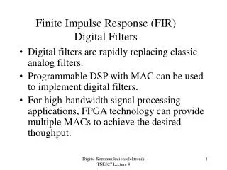
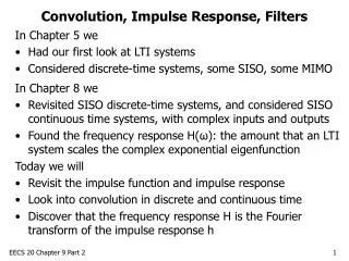
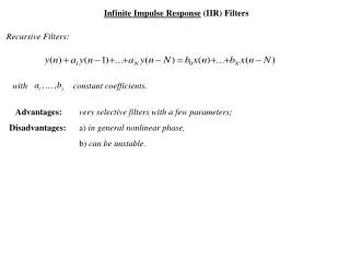
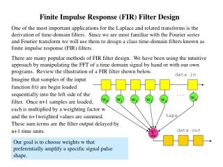
Finite Impulse Response (FIR) Filter Design One of the most important applications for the Laplace and related transforms is the derivation of time-domain filters. Since we are most familiar with the Fourier series and Fourier transform we will use them to design a class time-domain filters known as finite impulse response (FIR) filters. There are many popular methods of FIR filter design. We have been using the intuitive approach by manipulating the FFT of a time domain signal by hand or with our own programs. Review the illustration of a FIR filter shown below. data in Imagine that samples of the input function f(t) are begin loaded sequentially into the left side of the filter. Once n+1 samples are loaded, each is multiplied by a weighting factor w and the n+1weighted values are summed. These sum terms are the filter output delayed by n+1 time units. . . . wn w0 w1 w2 w3 w4 taps data out S Our goal is to choose weights w that preferentially amplify a specific signal pulse shape.
Building a Low-Pass FIR Filter In this example we will use our run_fft program to design and build a 15 tap low-pass time-domain filter. The FIR filter convolves the filter function (called the transfer function) with the signal function. We have learned that a convolution in the time-domain is equivalent to a product in the frequency domain and that, X(t) * h(t) = FFT-1[FFT(X(t)) x FFT(h(t))] We will use this fact to design the transfer function h(t). Since we are building a low-pass filter, we compute the (16 point) inverse FFT of a square window and rearrange the points to place the peak in the center right side left side
We apply the 15 tap FIR filter transfer function H(t) by sliding it along the input signal X(t) computing the sum of the products of signal terms and transfer function terms by, Output Xfilt(t) Input X(t) By comparing the amplitude of the FFT of X(t) and Xfilt(t) we can see that the low-pass FIR filter has attenuated the higher frequency sine wave component.