SOIPD
SOIPD. KEK-LBNL-Padova collaboration. Silicon On Insulator (SOI) detectors. ● CMOS electronics implanted on a thin silicon layer on top of a buried oxide (BOX): ensures full dielectric isolation, small active volume and low junction capacitance

SOIPD
E N D
Presentation Transcript
SOIPD KEK-LBNL-Padova collaboration SOIPD 2009
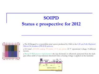
Silicon On Insulator (SOI) detectors ● CMOS electronics implanted on a thin silicon layer on top of a buried oxide (BOX): ensures full dielectric isolation, small active volume and low junction capacitance ● Radiation sensors can be built by using a high resistivity substrate and providing a technology to interconnect the substrate through the BOX SOI-2-IMAGER (2009) SOI-2 (2008) SOI-1 (2007) • 0.20um OKI FD-SOI technology • 256256 analog pixels (13.7513.75 um2) • 4 analog outputs • 5mm chip, 3.2mm active • Just delivered • 0.15um OKI FD-SOI technology • 16050 digital pixels (1010 um2) • 160100 analog pixels (1010 um2) • MIPs detection • First radiation damage tests • 0.20um OKI FD-SOI technology • 128172 digital pixels (2020 um2) • 40172 analog pixels (2020 um2) • Optimized for low leakage current • Currently under test SOIPD 2009
SOI-1 Tests on Analog and Digital Pixels Tests with a 1060nm IR laser (analog section) Tests with High Energy Particle Beam (digital section) Cluster pulse height • IR laser spot: 20um; • analog section tested for different Vd values; • signal pulse height measured in a 5×5 matrix, centered around the laser spot centre; • signal increases as √Vd as expected (increasing depletion region) until Vd ≃ 9 V, where it saturates; it decreases for Vd ≥ 15 (transistor back- gating). • IR laser spot: 5um; • pixel matrix scanned in 1um steps; • position reconstructed by the center of gravity of the reconstructed cluster charge; • resolution calculated by the spread of the reconstructed cluster position for events taken at each point in the scan and for different S/N values; • resolution scaled as the inverse of S/N, as expected (continuous line). Single Point Resolution • chip tested on the 1.35 GeV electron beam-line at the Advanced Light Source (ALS); • hit multiplicity observed in the digital pixels for events taken with and without beam • a clear excess of hits can be seen in the presence of beam SOIPD 2009
SOI-1 Radiation Hardness Tests Ionizing radiation Non Ionizing radiation • Irradiation performed at the LBNL 88-inch Cyclotron with 1-14 MeV neutrons on the analog pixel matrix; • study of the sensor noise before and after irradiation as a function of the depletion voltage at room temperature; • irradiation performed up to a total fluence of 1.2×10¹³ n/cm2; • a noise increase was observed after irradiation, varying from +25% for Vd= 5 V, to +52% for Vd = 20 V. This is interpreted as due to radiation-induced increase of leakage current in the sensor substrate • Irradiation performed at the BASE Facility of the LBNL 88-inch Cyclotron with 30 MeV protons on single transistors; • study of the variation in the threshold voltage for the nMOS test transistor as a function of the proton fluence; • irradiation performed up to a total dose of ≃ 600 kRad. • the total threshold variation is indeed significant ( 100 mV) also for a low substrate bias (i.e. Vd = 1 V). The effect is much larger than what would be expected at such doses from radiation damage in the transistor thin gate oxide and is clearly due to charge build-up in the thick buried oxide • similar results are obtained for the pMOSFET characteristics. An initial substrate voltage Vd = 5 V was used, but after a fluence of about 1×10¹² p/cm2 the transistor characteristics could not be properly measured, and a reduced substrate bias of Vd = 1 V needed to be apply in order to recover the transistor characteristics. Vd = 10V SOIPD 2009
SOI-1 Tests & Simulations Ids vs Vgs curve Experimental data TCAD simulation • Ids vs Vgs curve is drawn for different values of substrate bias • Threshold voltage is extracted from maximum gm in simulations (left plot) • Same procedure is used on experimental data (right plot) Vthreshold extraction • Backgating is much less effective in simulations • Hypothesis: BOX = large and extended gate ! are there some 3D effects (e.g. currents flowing on the side)? SOIPD 2009
Backgating reduction Experimental Data ●The substrate voltage acts as a back-gate, changing the transistor threshold until making it unable to work for voltages > 16V. PSUB ringsurrounding the transistorfloating ●The effectiveness of placing p+ implants close to the transistor to mitigate the problem has been investigated, both with simulation and with experimental measurements. TCAD Simulation PSUB ringsurrounding the transistorgrounded PSUB grounded actually limits the backgating effect! SOIPD 2009
SOI-2 Tests ●Radiation Damage Tests • X-ray irradiation on 0.20um technology transistors up to a total dose of 56 krad (SiO2) with Vback= 5V during irradiation; • PMOS transistors show no increment on leakage current; • leakage current for NMOS transistors is still at acceptable levels. ●Test on the detector • Analog pixels tested at LBNL ALS with 1.5 GeV e-: S/N~15-20 and ENC~20-30 e- up to 50 MHz clock frequency and Vdep=5 V (stronger effect of back-gating w.r.t. 0.15 mm process) • Digital pixels operable up to Vdep=35 V, proof of functionality achieved with 90Sr source Digital pixels 90Sr, Vdep = 35 V Analog pixels 1.5 GeV e-,Vdep = 2 V SOIPD 2009
SOI-2 Imager SOIPD 2009
3D detector SOIPD 2009
Attività 2010 • Caratterizzazione SOI imager come rivelatore particelle al minimo • Caratterizzazione SOI imager back-illuminated come rivelatore di fotoni • Studio back-gating via IEEM • Studio 3D detector • Seconda produzione SOI-3D SOIPD 2009
Progetto, disegno, test nuove mezzanine Test sensori Test beam Misura radiation hardness con IEEM Messa a punto IEEM 6 m/u Progettazione e test nuove mezzanine 3 m/u + 1 m/u CAD Test dispositivi 5 m/u Piccoli interventi OM 2 m/u Attività gruppo e servizi SOIPD 2009
Bisello RN 30 Candelori 30 Giubilato 30 Mattiazzo 30 Nigro 100 Silvestrin 100 Wyss 30 Gerardin 70 Mint 2 ke Mest 4 missioni LBL 1 missione KEK 1 conferenza 1 m/u test beam 15 Cons. qp produzione mat. test lab. mezzanine 40 SOIPD 2009