Download
1 / 38
380 likes | 410 Vues
Explore the definitions and concepts of stress in metal forming from a theoretical perspective. Learn how stress is calculated and its implications in mechanical engineering.

E N D
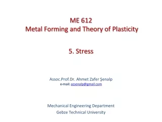
ME 612 Metal Forming and Theory of Plasticity 5. Stress Assoc.Prof.Dr. Ahmet Zafer Şenalpe-mail: azsenalp@gmail.com Mechanical Engineering Department Gebze Technical University
5.1. UniaxialStressDefinition 5. Stress Assuming continuousstructure limit can be written as: (5.1) Uniaxial nominal or engineering stress is obtained dividing load to the original cross sectional area: (5.2) Figure 5.1. Uniaxial tensile test. F force is applied perpendicular to A area. Original area before load application is Ao. Mechanical Engineering Department, GTU
5.1. UniaxialStressDefinition 5. Stress The uniaxial true stress σ is defined by dividing load to the current area at which the load is recorded; (5.3) Two definitions can easily be related; (5.4) Mechanical Engineering Department, GTU
5.2. Stress Definition in Three Dimensions 5. Stress We want to define the stress at a point O in a continuous body loaded by external forces : Figure5.2. Continuous body acted on by external forces. Mechanical Engineering Department, GTU
5.2. Stress Definition in Three Dimensions 5. Stress The first step is to “conceptually” cut the body into two pieces across a planethat passes from the point O. Let n be the unit vector normal to the surface generated by the cut as shown in Fig. 5.3. Figure 5.3. Internal forces acting on a plane whose normal is n. Here we show only one of the pieces of the body that resultsfrom the above cut. The forces acting on the cut surface are the internal forces transmittedfrom the other piece and are necessary to maintain the two pieces in static equilibrium. Mechanical Engineering Department, GTU
5.2. Stress Definition in Three Dimensions 5. Stress For the plane cut shown, let us define (as we did with the 1D stress definition) the traction vectortn as: (5.5) Here: : is the internal force acting in a small area ΔA around the point O : a small area ΔA around the point O : is ‘force intensity’ or ‘stress’ acting on a plane whose normal is n at the pointO. Mechanical Engineering Department, GTU
5.2. Stress Definition in Three Dimensions 5. Stress If we consider a fixed Cartesian coordinate system x, y, z with unit vectors nx,ny,nz, then, we can write the components of the traction vector tn as follows: (5.6) We say that we know the state of stress at a point if for any plane passing through thatpoint we can calculate the traction vector. Above we calculated the traction tn at the pointO through the plane with normal n. It turns out that if we know the traction vector(force per unit area) in three mutually perpendicular planes through point O,then we can always calculate the traction vector at any other plane through O. Mechanical Engineering Department, GTU
5.2. Stress Definition in Three Dimensions 5. Stress Select n=nx,ny,nz (unit vectors in the x, y and z axes, respectively). This defines threetractions (forces/unit area) (tnx, tny , tnz) acting on the yz, xz and xy intersection planes,respectively. Each of these traction forces has three components. In particular, we can write the following: Mechanical Engineering Department, GTU
5.2. Stress Definition in Three Dimensions 5. Stress Equation (5.7) is graphically shown in Fig. 5.4 and similar representations are applied for equations (5.8) and (5.9). We define the stress components to be nothing else but the x, y, and zcomponents of the traction vectors tnx,tny,tnz as given in equations (5.7),(5.8) and(5.9). Figure 5.4. Stress components on positive x face at point O. Mechanical Engineering Department, GTU
5.2. Stress Definition in Three Dimensions 5. Stress Figure 5.5. Definition of positive and negative cube faces. Mechanical Engineering Department, GTU
5.3. StressTensor 5. Stress In a matrix form, the “stress at the point O” is denoted as follows: and this representation is called stress tensor. Mechanical Engineering Department, GTU
5.3. StressTensor 5. Stress There are 4 properties that makes stress, tensor. These are: • Magnitude • Direction • Plane of action • Line of action In expression; i: Direction j: The normal direction of plane of action Mechanical Engineering Department, GTU
5.3. StressTensor 5. Stress Traction tnx is applied to yz plane. Component of thisis and it is in x direction (perpendicular to yz plane). , , normal stress components. The rest are ; shear stress components. Mechanical Engineering Department, GTU
5.4. TheEquations of ForceEquilibrium 5. Stress Unit cube given in Figure 5.6 with length of sides dx, dy, dz. The stress components acting on each face is shown. Figure 5.6. Stress components referred to Cartesian coordinates Mechanical Engineering Department, GTU
5.4. TheEquations of ForceEquilibrium 5. Stress In Figure 5.7 stress components in cylindrical coordinates are shown. Force balance can also be written in terms of cylindrical coordinates similar to Cartesian coordinates. Figure 5.7. Stress components referred to cylindrical coordinates Mechanical Engineering Department, GTU
5.4. TheEquations of ForceEquilibrium 5. Stress The rates of change of the stress components with increase in x on area dAx , when y and z are kept constant are; , and (5.11) Similar expressions for directions y and z are; Mechanical Engineering Department, GTU
5.4. TheEquations of ForceEquilibrium 5. Stress There are thus 18 forces on the 6 sides of the block and the conditions for equilibrium may be found by considering the forces in each of the directions parallel to the axes. Examining conditions for equilibrium in direction Ox, ( 5.12) And thus simplifying; (5.13) İs obtained. Mechanical Engineering Department, GTU
5.4. TheEquations of ForceEquilibrium 5. Stress Figure 5.8. Force equilibrium in OX Mechanical Engineering Department, GTU
5.4. TheEquations of ForceEquilibrium 5. Stress Theremaining 2 equations of equilibrium, i.e. Fordirections Oy andOzare; (5.14) (5.15) Shortly can be expressed in; (5.16) form. If body forcesareincludedequation 5.16 can be written as. r İs density is body force. Mechanical Engineering Department, GTU
5.5. CoupleEquilibrium 5. Stress The condition for moment or couple equilibrium is next determined. In Figure 5.9 are shown the stresses acting so as to tend to rotate the block about a line through P parallel to Oz. Figure 5.9. Couple equilibrium in plane XY Mechanical Engineering Department, GTU
5.5. CoupleEquilibrium 5. Stress If these are in equilibrium; (5.18) On simplifying; (5.19) Similarly for the other two directions; (5.20) (5.21) Mechanical Engineering Department, GTU
5.5. CoupleEquilibrium 5. Stress These equations may again be summarized as; (5.22) Hence; (5.23) The unkown stress component decreases to 6 in the above tensor. Mechanical Engineering Department, GTU
5.6. ThreeDimensionalStressSystems 5. Stress The 6 components of stress at apoint being given in magnitude and direction as in Figure 5.10. Suppose it is desired to evaluate the normal and shear stress on any doubly oblique plane, or in particular the principal stresses and their directions at that point. Principal stresses are stresses acting normal to a plane across which there is no shear stress. Let the doubly oblique plane be represented by triangle ABC. Figure 5.10. Stresses on a doubly oblique plane Mechanical Engineering Department, GTU
5.6. ThreeDimensionalStressSystems 5. Stress ABC has normal ON has directioncosines . Denote by S the resulting stress on triangle ABC, which has direct stress component Sn normal to plane ABC and a shear component Ss in the plane ABC. SX, SY, SZ are components of S parallel to Ox,Oy,Oz respectively. Figure 5.10. Stresses on a doubly oblique plane Mechanical Engineering Department, GTU
5.6. ThreeDimensionalStressSystems 5. Stress D denotes the area of the triangle ABC and Dx, Dy, Dz, the areas of triangles OBC, OAC, OAB. For equilibrium of forces on the tetrahedron in the direction Ox, Figure 5.10. Stresses on a doubly oblique plane Mechanical Engineering Department, GTU
5.6. ThreeDimensionalStressSystems 5. Stress (5.24) (5.25) because and therefore, is the angle between ON and Ox. Mechanical Engineering Department, GTU
5.6. ThreeDimensionalStressSystems 5. Stress Similarly, (5.26) (5.27) and now, (5.28) Utilizing equations 5.25, 5.26 and 5.27 and further, (5.29) Equations 5.28 and 5.29 yield the normal and shear stress on any defined plane when general state of stress at a point is given. Mechanical Engineering Department, GTU
5.6. ThreeDimensionalStressSystems 5. Stress If Sn is a principal stress, say s, i.e. Ss=0 , S=Sn . And Sn ’s direction is (l,m,n) then by resolving the directions OX, Oy, Oz respectively If (5.30) and (5.31) are solved for m/l and n/l and these values are substituted into (5.32), a relation between the coefficients of l,m,n in these equations results. Only if this relation is fulfilled with equations 5.30, 5.31, 5.32 be satisfied and then it is found that; (5.30) (5.31) (5.32) (5.33) Mechanical Engineering Department, GTU
5.6. ThreeDimensionalStressSystems 5. Stress This cubic equation in a real physical situation has 3 real solutions which are the principal stresses, say of this particular stress system. (5.34) Here I1, I2, I3 are invariants and they are independent of the coordinate system chosen. Below the quantities mentioned by ‘ belong to a coordinate system (x’,y’,z’) which has the same origin with xyz coordinate system. (5.35) (5.36) (5.37) Mechanical Engineering Department, GTU
5.6. ThreeDimensionalStressSystems 5. Stress In case using principal stresses equations (5.35), (5.36) and (5.37) reduces to; Hydrostatic stress; is; (5.41) then (5.42) I1 is called hydrostatic component. I1 does not effect yield but delays rupture. Hence yield criteria is not a function of I1. (5.38) (5.39) (5.40) Mechanical Engineering Department, GTU
5.6. ThreeDimensionalStressSystems 5. Stress A stress can be decomposed to deviatoric stress component and hyrostatic component. (5.43) Then deviatoric stress is ; (5.44) In equations (5.38), (5.39) and (5.40) instead of s replaced , İs obtained. The obtained J2 value will be used as Von Mises yield criteria. (5.46) (5.47) (5.48) Mechanical Engineering Department, GTU
5.7. StressTransformationandMohr’sCircle forPlaneStressProblems 5. Stress Consider the xy plane to be the plane of a thin sheet.The state of stress at a given pointcan be approximated to depend only upon the four stress components σxx, σxy, σyx, and σyythat are considered to be functions of only the x and y. • Figure 5.11. Elements in plane stress. sx and sy are here the x and y components, respectively,of the traction vector in the plane AB. Mechanical Engineering Department, GTU
5.7. StressTransformationandMohr’sCircle forPlaneStressProblems 5. Stress The stress components σzz = σzx =σzy =0, i.e. all the out of the xy plane stress components are zero. Since the only non zerostress components are on the xy plane, we call this state plane stress in the xy plane. (Notethat in terms ofprincipal stresses, plane stress means that one of the principal stresses iszero). Consider a square element (the plane version of the cube) in plane stress. Letus consider a coordinate system x’ and y’ (on the plane xy) such that is the angle betweenthe x’ axis and the x axis. From equilibrium of forces in the triangular QAB , it canbe shownthat: (5.49) (5.50) Mechanical Engineering Department, GTU
5.7. StressTransformationandMohr’sCircle forPlaneStressProblems 5. Stress To calculate yıyı , you can use equ. 5.49 with +/2 instead of . Finally: (5.51) Recall that in the above plane stress state the z axis is a principal stress axis. To define theother two principal directions in the xy plane, we can use eq. (5.50) with τxy = 0 to calculatetheprincipalangleθ. From xıyı= 0, one can show that the direction of principal axes is given from: (5.52) while the principal in plane stresses are given as follows: (5.53) Mechanical Engineering Department, GTU
5.7. StressTransformationandMohr’sCircle forPlaneStressProblems 5. Stress To find the maximum in plane shear stress (i.e. the maximum shear stress in the plane xy) take dτθ /dθ =0 (use equ. (5.50)), find the angle θ and then substitute back into equ. (5.50). Wefinally can show the following: (5.54) Figure 5.12. (a) Stress element and (b) Mohr’s circle for a plane stress state. Mechanical Engineering Department, GTU
5.7. StressTransformationandMohr’sCircle forPlaneStressProblems 5. Stress Figure: 5.13. The Mohr circle provides both normal stresses xıxı = and yıyı= ıas wellas the shear stress τx’y’ = τθ. For the above plane stress state, it is simple to use the so called Mohr Circle to perform stress transformations. Mechanical Engineering Department, GTU
5.7. StressTransformationandMohr’sCircle forPlaneStressProblems 5. Stress The basic rules for using the Mohr circle are as follows: • Normal stresses are plotted to scale along the abscissa, where tensile is positive andcompressive is negative (Figures 5.12 and 5.13). • Shear stresses are plotted along the ordinate. A shear stress that induces clockwiserotation of the stress element is plotted as if it were positive, while one causing counterclockwiserotation as if it were negative. • Angles between planes or directions represented on the circle plot are double the correspondingangles on the physical plane. By using figure 5.12 the above eqautions can be derived. Mechanical Engineering Department, GTU
5.7. StressTransformationandMohr’sCircle forPlaneStressProblems 5. Stress Calculation of the maximum shear stress at a point using the principalstressvalues: Above we calculated the maximum in plane shear stress but not necessarily the maximumshear stress in all planes! Let the principal stresses be ordered as follows: 1 23.Then the maximum shear stress τmax in any plane through the point is given as: (5.55) The maximum shear stress acts on a plane that makes an angle of 45o degrees with theplanes in which the principal stresses σ1 and σ3 act. Note that in eq. (5.55) the algebraic sign for shear stresses is maintained, i.e. if a principalstress is compressive, then a negative value will be entered in its value in eq. (5.55). Mechanical Engineering Department, GTU