Download
1 / 32
320 likes | 460 Vues
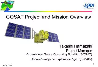
GOSAT FTS Design and BBM Test Results May 18, 2005 Quebec, Canada Akihiko KUZE (JAXA). Instrument Design. S atellite Configuration. Greenhouse Gases Observing Sensor. Cloud Aerosol Sensor. Mission Sensor System. Greenhouse Gases Observing Sensor. Cloud and Aerosol Sensor.

E N D
GOSAT FTS Design and BBM Test Results May 18, 2005 Quebec, Canada Akihiko KUZE (JAXA)
Satellite Configuration Greenhouse Gases Observing Sensor Cloud Aerosol Sensor
Mission Sensor System Greenhouse Gases Observing Sensor Cloud and Aerosol Sensor UV, Visible, SWIR imager SWIR and TIR FTS
Observation Method TIR-FTS SWIR-FTS Stratospheric aerosol Cloud GHG Tropospheric aerosol Earth’s surface Simultaneous Observation of (1) CO2 differential absorption of solar scattered light and (2) thermal radiation from GHG and surface.
Data flow Interferogram FTS Inverse FTF Source and sink of 22 area Global distribution CO2 and CH4 absorption spectra
Instrument Configuration Scene flux Cooler and detector Solar diffused flux Pointing mechanism (main) Blackbody Deep space view FTS Switching mirror Pointing mechanism (backup) Camera for identifying FTS field of view
Operation • Solar Irradiance Cal. FTS SWIR & TIR CA-imager • Lunar Cal Solar Flux • FTS TIR Observation Mode Sun Glint Pointing Mode
Foot prints GPS 5 cross track patters 1, 3, 5, 7, 9 points/cross track scan GPS receiver GOSAT Star Tracker Pointing Mechanism 88 – 800 km Satellite Direction (along track) Cross track
Polarization Measurements • (1) Advantage of the Polarization Measurements • use of the polarization information • accurate measurements (correction of the polarization sensitivity change on orbit) • redundancy • (2) Drawback • loss of SNR • complicated analysis
Polarization Model Polarization model of the observation with FTS
Polarization Measurements with FTS Polarization of Scene Flux East BackScattering Low Polarization West High Polarization Ground (small polarization)
FTS Optics and Polarization Rotary Actuator Flexible blade ZnSe beam splitter (major polarization source) Corner Cube (aperture stop) Diode laser sampling system S-Polarization P-Polarization
Band separation aft optics (band and polarization separation) DF1 DF2 DF3 MCT(B4) (TIR) BPF2 BPF1 BPF3 InGaAs (B2) P,S Si (B1) P,S InGaAs (B3) P,S Test piece for GOSAT FTS Band 3 (2.0 micron) Polarization Beam Splitter for SWIR
FTS BBM optics configuration FTS Detector and band separation optics Pre-Amplifiers Camera for identifying FTS field of view Sampling Laser 1.31 micron Diode Scene flux
2.0 micron SNR performance (Spectralon surface) CO2, CH4 in-situ measurements Simultaneous Measurements with air borne in-situ measurements.
1.6 micron SNR performance (Spectralon surface) High spectral resolution data with high SNR for retrieval algorithm check.
0.76 micron SNR performance (Spectralon surface)
SNR Performance (Surface Reflection) FTS scene photo with CCD camera Target: Dead grass Target estimated albedo 0.3-0.4, SNR=100 (single shot)
Spectral Resolution (Diode Laser) FWHM=0.24 cm-1 (equal to the theoretical value) The required performance was achieved.
Polarization Sensitivity (BBM) 0.76micron 1.6 micron 2.0 micron BBM measured data with polarizer. Instrument polarization sensitivity is about 25 %. Polarization is mainly from FTS-BS (bare ZnSe).
Spectral Resolution (Gas Cell) 60506090cm-1 CH4 Gas Cell (150 Torr 1m) MOPD=±2.5cm Dec. 8, 2004 at NIES
Air Plane Campaign with BBM Fly over the aerosol layer and thin cloud
Air Plane Campaign with BBM CO2 1.6 micron BBM Cessna flight data over the rice field (at the altitude of 3000m) 2004/08/10 14:28 0810_2_10000f1.Interferogram No.59(0.2cm-1,fringe rate=50) The first spectra acquired above from the aerosol layer.
Air Ship Campaign BBM: Airship Campaign