GMPLS Hands-On Workshop
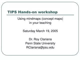
GMPLS Hands-On Workshop. Presented at NASA Ames Research Center May 30 and 31, 2007. Welcome!. This is the 3 rd GMPLS DCS Hands-ON Workshop The objective of this workshop is two fold:


GMPLS Hands-On Workshop
E N D
Presentation Transcript
GMPLS Hands-On Workshop Presented at NASA Ames Research Center May 30 and 31, 2007
Welcome! • This is the 3rd GMPLS DCS Hands-ON Workshop • The objective of this workshop is two fold: • Disseminate and incubate GMPLS control plane design and engineering concepts to the R&E networking community, • Obtain direct feedback from the community on how to improve the technologies…Hopefully, to help guide future development and deployment priorities and speed adoption
Why do a workshop? • Dynamic Hybrid Networks are new… • The service concepts are still evolving… • The software and hardware implementations are still evolving… • Even the standards are still evolving… • The networks that support these capabilities are few…so far. • The user base is small [for now]…. But will grow as the capabilities mature and become more ubiquitous, persistent, and robust and the utility of both connection oriented services and dynamic provisioning becomes more widely recognized and accepted. • Providing hands-on experience to design and deploy these architectures is one way to broaden and promote adoption.
Agenda • Day 1 • 9am Overview of GMPLS • 10am Exercise #1: Designing the Control Plane • 11am Building the Control Plane • 12noon Lunch • 1pm Debugging the Control Plane • 2pm Exercise #2: NARB and Local-ID • 5pm Adjourn • 7pm Dinner • Day 2 • 9am Exercise #3: Inter-Domain Routing and Signaling • 12noon Lunch • 1pm Exercise #4: ASTs and XML Interface • 3:30Pm Wrap up • 4pm Adjourn
Workshop Perspective • In this workshop we focus on implementation • We will design and build a multi-domain GMPLS controled ethernet network • We have a mobile GMPLS test and evaluation lab consisting of 24 PCs and 12 switches • We will be focused on the GMPLS control plane issues • Specifically, OSPF and RSVP • We will do a very brief and cursory review of RSVP and OSPF. • For detailed information on the protocols themselves see the IETF RFCs. • We will not deal with ISIS or CR/LDP or LMP • We do not cover alternate control plane models other than to note where work is being done in related emerging areas • We use open source software developed by the DRAGON Project • Adapted versions of KOM-RSVP and Zebra OSPF plus new tools and features • This software is the only GMPLS software available to support dynamic ethernet services • This software is being adapted and deployed by Internet2 to support dynamic circuit services. • It is being ported to support a wide variety of vendor equipment (e.g. Force10, Extreme, Dell, Ciena, Cisco, Raptor)
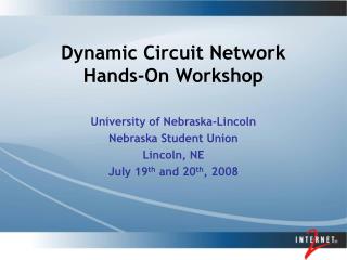
NARB 10.1.21.2 10.2.22.1 GRE21 10.1.21.1 NARB GRE11 6 10.4.24.2 6 D11 D12 GRE22 6 GRE24 7 10.2.22.2 10.4.24.1 D14 10.3.23.2 10.3.23.1 GRE23 NARB NARB 5 GRE14 10.3.13.1 GRE13 10.3.13.2 6 D13 7 6 A Simple GMPLS Network GRE6 10.a.6.2 VLSR2-PC 10.a.6.1 GRE2 10.a.2.2 GRE4 .6 10.a.4.1 VLSR2-SW VLSR1-PC VLSR3-PC 10.a.4.2 .5 GRE6 10.a.6.2 10.a.2.1 eth0 .4 3 10.a.3.2 .8 VLSR2-PC 1 4 10.a.6.1 11.a.4.1 D2 GRE2 10.a.2.2 10.a.5.1 11.a.2.2 10.a.1.2 10.a.3.1 GRE4 VLSR3-SW .6 10.a.4.1 VLSR1-SW D4 4 GRE3 .7 11.a.2.1 11.a.4.2 4 .3 VLSR2-SW 3 1 11.a.3.1 11.a.5.1 1 3 5 5 11.a.1.2 GRE5 VLSR1-PC VLSR3-PC 10.a.4.2 11.a.3.2 D1 .5 10.a.2.1 D5 eth0 .4 3 10.a.3.2 11.a.5.2 10.a.5.2 11.a.1.1 .8 1 4 10.a.1.1 D3 11.a.4.1 .9 eth0 eth1 eth1 D2 eth0 .2 10.a.5.1 11.a.2.2 10.a.1.2 10.a.3.1 VLSR3-SW VLSR1-SW D4 4 GRE3 .7 11.a.2.1 11.a.4.2 4 .3 3 1 11.a.3.1 11.a.5.1 1 3 5 5 11.a.1.2 GRE5 11.a.3.2 D1 D5 11.a.5.2 10.a.5.2 11.a.1.1 10.a.1.1 D3 .9 eth0 eth1 eth1 eth0 .2 GRE6 10.a.6.2 VLSR2-PC 10.a.6.1 GRE2 10.a.2.2 GRE4 .6 10.a.4.1 VLSR2-SW VLSR1-PC VLSR3-PC 10.a.4.2 .5 GRE6 10.a.6.2 10.a.2.1 eth0 .4 3 10.a.3.2 .8 VLSR2-PC 1 4 10.a.6.1 11.a.4.1 D2 GRE2 10.a.2.2 10.a.5.1 11.a.2.2 10.a.1.2 10.a.3.1 GRE4 VLSR3-SW .6 10.a.4.1 VLSR1-SW D4 4 GRE3 .7 11.a.2.1 11.a.4.2 4 .3 VLSR2-SW 3 1 11.a.3.1 11.a.5.1 1 3 5 5 11.a.1.2 GRE5 VLSR1-PC VLSR3-PC 10.a.4.2 11.a.3.2 D1 .5 10.a.2.1 D5 eth0 .4 3 10.a.3.2 11.a.5.2 10.a.5.2 11.a.1.1 .8 1 4 10.a.1.1 D3 11.a.4.1 .9 eth0 eth1 eth1 D2 eth0 .2 10.a.5.1 11.a.2.2 10.a.1.2 10.a.3.1 VLSR3-SW VLSR1-SW D4 4 GRE3 .7 11.a.2.1 11.a.4.2 4 .3 3 1 11.a.3.1 11.a.5.1 1 3 5 5 11.a.1.2 GRE5 11.a.3.2 D1 D5 …(Just kidding…) 11.a.5.2 10.a.5.2 11.a.1.1 10.a.1.1 D3 .9 eth0 eth1 eth1 eth0 .2
Instructors and Friends • Jerry Sobieski (MAX) • Chris Tracy (MAX) • These people are intimately involved in numerous projects related to deploying dynamic control planes: • NSF DRAGON • Internet2 HOPI Testbed and the new Dynamic Circuit Service • DICE (Dante, Internet2, Canarie, Esnet) - International
GMPLS Snapshot • Generalized Multi-Protocol Label Switching – GMPLS • Evolved from MPLS concepts, and experiences gained from deployments within the IP packet world • GMPLS extends Traffic Engineering (TE) concepts to the multiple layers: • Packet Switching Capable (PSC) – standard MPLS LSPs • Layer2 switch capable (L2SC) – Ethernet and VLANs • TDM switch capable (TDM) – SONET/SDH • Lambda switching (LSC) – Wavelength • Fiber Switch capable (FSC) • In the GMPLS, any network element that supports one of the above switching capabilities and participates in the GMPLS control plane protocols is refered to as a “Label Switching Router” or LSR. • GMPLS Protocols: • Routing: GMPLS-OSPF-TE • Signaling: GMPLS-RSVP-TE • Link layer: LMP • ISIS and CR/LDP are also considered part of the GMPLS protocols • In this workshop we will focus only on OSPF and RSVP
OSPF – “Open Shortest Path First” • OSPF is a “Link State” Routing Protocol • OSPF routers discover each other thru a HELLO protocol exchanged over OSPF interfaces • Routers identify themselves with a “router id” (typically the loopback IP address or another unique IP address is used) • OSPF routers flood Link State Announcements (LSAs) to each other that describe their connections to each other and that specify the current link state of these connections • In the GMPLS and TE extensions to OSPF, the LSA contains information about the available bandwidth, routing metrics, switching capabilities, encoding types, etc. • LSAs are not flooded in the direction from which they are heard • OSPF routing is often divided into “areas” to reduce or limit LSA flooding in large networks • Each OSPF router in an area has a full topological view of its area • SPF identifies the next-hop for each known destination prefix
CSPF • Constrained Shortest Path First • In OSPF TE, reachability is no longer the only criteria for deciding next-hop • E.g. Bandwidth available on each intemediate link could be a constraint used to identify or select a path • In GMPLS, with multiple switching capabilities, there are many constraints to be considered • Path Computation is used differently for selecting circuit layout than for selecting the next-hop for shortest path packet forwarding • Two identical path requests may generate two completely separate paths (unlike traditional routed IP which would select only the single “best” path for forwarding packets) • Paths are not computed until or unless a path is needed. • Some GMPLS service models do propose precomputing paths (or at least next-hops) based on certain apriori assumptions about the LSP – the tradeoff is generally one of scheduled “book ahead” reservations vs fast “on-demand” provisioning.
RSVP – ReSerVation Protocol • GMPLS-RSVP-TE is the signaling (provisioning) protocol used to instantiate a Label Switched Path (LSP) thru the network • Five basic RSVP messages we will reference: • PATH = First message issued by the source towatrds the destination requesting a connection be established • RESV = Response from the destination towards the source accepting the connection • PATH_TEAR = Message sent to tear down an LSP • PATH_ERR = Error message sent when a PATH request is denied or encounters a problem • REFRESH = Message sent between LSRs indicating a connection is still active (prevent timeout and deletion)
Path Computation Element • In GMPLS, the Path Computation Element (PCE) is separated from the routing protocol. • The routing protocol ditributes topology information and builds the topology database that contains all the [visible] resources and their state – the Traffic Engineering Data Base (TEDB) • PCE is responsible for processing the TEDB to select a path through the network that meets the constraints specified in the service request (e.g. BW, encoding, Src/Dst, Policy, etc.) • In GMPLS, the path so computed is expressed as an “Explicit Route Object” (ERO). • An ERO is simply a data structure that contains a sequentially ordered list of routers (LSRs) that the path will travers from Source to Destination • A “Loose Hop” ERO specifies a partial set of transit nodes – the path may include other nodes as long as it passes through the specified nodes in order. • A “Strict Hop” ERO specifies a complete list of transit nodes – no other intervening nodes are allowed. • RSVP includes the ERO in the PATH message to pin the path through specific nodes
What is the Control Plane? • The Control Plane is the network facilities and associated protocols that select, allocate/deallocate, and provision network resources to fulfil a user service request. • Typically this includes routing protocols that distribute topology and reachability information among interconnected networks and network elements • It aslo includes other function that allocate appropriate resources and put those resources into sewrvice (Path computing and signalling) • With GMPLS, routing and signaling messages between LSRs do not travel along the same path as the circuit being established. • The set of facilities between LSRs that carry the data circuits themselves is called the “Data Plane” • The set of facilities between LSRs that carry the routing and signaling protocols is called the “Control Plane” • It is good practice to design the control plane so as to be highly robust and impervious to effects of other network traffic. • In the olden days of SS7, the control plane was a completely congruent but separate network from the data plane for phone calls. • In this workshop, we will design a control plane that is congruent with the data plane • Some exceptions will be noted for hierarchichally routed domains.
CP CP CP Control Plane and Data Plane Control Plane GMPLS Protocols GMPLS Protocols Label Switched Paths Label Switched Paths Data Plane
The Virtual Label Switching Router VLSR • The DRAGON Project proposed to cover ethernet switches with PCs running the open source GMPLS protocols, and re-configuring the switches on the fly using SNMP Mgmt Interface Operations Access Switch Control Plane Linux Control PC Control Links Via GRE tunnels Linux Control PC SNMP Ethernet Switch Data Plane Core Ethernet Switch VLSR - conceptual VLSR – physical
Control Processor Label Switching Fabric A [Typical] Label Switching Router - LSR Management Interface Switching Fabric Interface Link Data Interfaces
C7 R6 C5 R3 D7 C1 D5 D1 C3 C6 R5 D3 C2 D6 R1 C4 D2 D4 R2 R4 Laying Out the Control Plane • Lay out the data plane between NEs first. • For now, we are going to ignore intervening static NEs. • Make sure all Nes and links are uniquely labeled • Then, control links connect the dynamic network elements • If you are including end systems in the dynamic network, you should add them where appropriate S D8 C8 D9 C9 D
Control Plane • Often, the dynamic network elements are not directly adjacent to one another – but the control structure expects them to be (at least logically adjacent) • We employ Generic Routing Encapsulation (GRE) tunnels for the control links in order to create logical adjacencies • GRE Tunnels are set up between two IP hosts. (these are the “tunnel endpoints”) • They present a pseudo interface to the end host that appears to be directly linked to the remote endpoint, thus allowing a single common IP subnet to be allocated on this pseudo interface. R1 R2 R3 GRE Tunnel Endpoints Control Link Endpoints Data plane
Workshop Laboratory • Four “Pods”: Red, Blue, Yellow, Green • Each Pod represents an independent network domain • Each Pod has two End Systems: ES1 and ES2 • Each Pod has three Virtual LSRs (VLSRs) • Each VLSR has a PC (for ctrl plane) and a Ethernet switch (for data plane) • Each Pod has one PC for interdomain routing support of the NARB • The PCs are running Debian Linux • We have installed it and all the software required to download, build, and run the DRAGON software, and to perform the workshop labs • We installed the DRAGON software • /usr/local/dragon/{bin,etc,workshop}
Basic Pod Data Plane Ethernet Switch ES1 ES2 End System
Pod Network Elements Network Aware Resource Broker- “NARB” NARB Virtual Label Switching Router- “VLSR” VLSR2 VLSR3 VLSR1 VLSR3-PC VLSR1-PC VLSR3-SW VLSR1-SW ES1 ES2 End System
Management Addressing “Red” pod: ASN=1 “Blue” pod: ASN=2 “Yellow” pod: ASN=3 “Green” pod: ASN=4 Workshop Gateway Router 192.168.1.1 Management VLAN 192.168.<asn>.n/16 .10 NARB VLSR2 .6 VLSR1 VLSR3 .5 eth0 .4 .8 D2 D4 .7 .3 D1 D5 D3 .9 eth0 eth1 eth1 eth0 .2 ES1 ES2 Management VLAN 192.168.<asn>.n/16 GRE<x> = 10.<asn>.<x>.n / 30 GRE7= 10.1.7.0 / 30 Dynamic Data plane port group = g3-g24 Dynamic VLAN range = 100…200 TEaddr = 11.<asn>.<x>.n / 30
GW2 GW1 SW2 SW1 NARB NARB VLSR1-PC VLSR1-SW VLSR1-SW VLSR1-PC VLSR2-PC VLSR2-SW VLSR2-SW VLSR2-PC VLSR3-PC VLSR3-SW VLSR3-SW VLSR3-PC ES1 ES1 ES2 ES2 NARB NARB VLSR1-PC VLSR1-SW VLSR1-SW VLSR1-PC VLSR2-PC VLSR2-SW VLSR2-SW VLSR2-PC VLSR3-PC VLSR3-SW . VLSR3-SW VLSR3-PC ES1 ES1 ES2 ES2 Rack Layout 123456789012345678901234567890 123456789012345678901234567890 Rack 2 Rack 1
Exercise #1 VLSRs for the Masses • Diagram a control plane for each pod • Fill out the template for addressing scheme • Connect the dots • Configure the software • Set up an LSP • …and if that fails…read the instructions.
Workshop Testbed “Pod” “Red” pod: ASN=1 “Blue” pod: ASN=2 “Yellow” pod: ASN=3 “Green” pod: ASN=4 Workshop Gateway Router 192.168.1.1 GRE4 Management VLAN 192.168.<asn>.n/16 .10 NARB GRE6 10.a.6.2 VLSR2-PC 10.a.6.1 GRE2 10.a.2.2 .6 10.a.4.1 VLSR2-SW VLSR1-PC VLSR3-PC 10.a.4.2 .5 10.a.2.1 eth0 .4 3 10.a.3.2 .8 1 4 11.a.4.1 D2 10.a.5.1 11.a.2.2 10.a.1.2 10.a.3.1 VLSR3-SW VLSR1-SW D4 4 GRE3 .7 4 11.a.2.1 11.a.4.2 .3 3 1 11.a.3.1 11.a.5.1 GRE1 1 3 5 5 GRE5 11.a.1.2 11.a.3.2 D1 D5 11.a.5.2 10.a.5.2 11.a.1.1 10.a.1.1 D3 .9 eth0 eth1 eth1 eth0 .2 ES1 ES2 Management VLAN 192.168.<asn>.n/16 Dynamic Data plane port group = g3-g24 Dynamic VLAN range = 100…200 GRE<x> = 10.<asn>.<x>.n / 30 GRE7= 10.1.7.0 / 30 TEaddr = 11.<asn>.<x>.n / 30
Command Line Interface ports • dragond 2611 • ospfd 2604 (intra-domain) • ospfd 2614 (inter-domain) • narb 2626 • rce 2688 > telnet localhost 2611
RSVP S PATH(S,D) R6 R3 R5 R1 D R2 R4
Review • Control plane design process: • Diagram intradomain data plane, enumerate the data links • Diagram a congruent control plane, enumerate the GRE links associated with each data link • Assign IP addresses to control links, identify the tunnel end points • Assign addresses to the TE-links • Implementation: • Realize the data plane • Setup the GRE tunnels • Configure the VLSRs • Configure the NARB • Test
Day 2: • Inter-domain NARB • Design (and implement) the inter-domain Data plane • Layout the inter-domain control plane • Configure the inter-domain OSPFd • Describe the “abstract topology” that NARB will advertise to external peers • Test • Application Specific Topologies
The NARB Server Inter-Domain adjacencies Inter-ospfd User Interface narbd rce Intra-ospfd Intra-Domain adjacency
10.1.21.2 ASN 2 10.2.22.1 GRE21 10.1.21.1 ASN 1 GRE11 10.4.24.2 D11 GRE12 D12 GRE22 GRE24 10.2.22.2 10.4.24.1 D14 10.3.23.2 10.3.23.1 ASN 3 GRE23 GRE14 10.3.13.1 GRE13 10.3.13.2 ASN 4 11.3.13.1 D13 11.3.13.2 Inter-Domain Logical Topology NARB NARB 6 6 6 7 NARB NARB 5 6 7 6 Intra-domain ctrl plane Inter-domain ctrl plane Data plane
Exercise #3 Interdomain Configuration • Layout of the Inter-domain data plane and control plane • Identify data paths between edge LSRs for LSP provisioning • Establish control links between edge LSRs for RSVP signaling • Establish control links between NARBs for interdomain peering • Configuration of the NARB abstract topology • Suggest for this exercise we use full topology (should be present in config files – just needs verification) • Test LSP setup
NARB 10.1.21.2 ASN 2 10.2.22.1 GRE21 10.1.21.1 NARB ASN 1 GRE11 6 10.4.24.2 6 D11 GRE12 D12 GRE22 6 GRE24 7 10.2.22.2 10.4.24.1 D14 10.3.23.2 10.3.23.1 ASN 3 GRE23 NARB NARB 5 GRE14 10.3.13.1 GRE13 10.3.13.2 6 ASN 4 11.3.13.1 D13 7 6 11.3.13.2 Intra-domain ctrl plane Inter-domain ctrl plane Data plane Exercise #4 Triangle AST Detail eth1.110 eth1.111 Blue-es2 eth1.110 eth1.112 Red-es1 eth1.112 eth1.111 Green-es1
Application Specific TopologyXML Description • <topology action="SET UP_REQ"> • <resource type="pc" name="red-es1"> • <ip>192.168.1.2</ip> • <router_id>192.168.1.2</router_id> • </resource> • <resource type="pc" name="red-es2"> • <ip>192.168.1.9</ip> • <router_id>192.168.1.9</router_id> • </resource> • <resource type="non_uni" name="red-es1-es2"> • <src> • <es>red-es1</es> • <assign_ip>14.14.14.1/30</assign_ip> • </src> • <dest> • <es>red-es2</es> • <assign_ip>14.14.14.2/30</assign_ip> • </dest> • <te_params> • <bandwidth>eth100M</bandwidth> • <swcap>l2sc</swcap> • <encoding>ethernet</encoding> • <gpid>ethernet</gpid> • </te_params> • </resource> • </topology>
the “baselines” E-science Application: Very Long Baseline Interferometry “E-VLBI” Aggregated streams at correlator: 2005 > 2 Gbs 2007 ~ 10 Gbs to 20+ Gbs 2010 > 40+ Gbs Radio Telescopes source b/w: 2005 = 512 Mbs 2007 = 2 Gbs 2010 > 4+ Gbs
Dwingeloo, NL MIT Haystack, US C C Jodrel Bank, UK Westerbork,NL W V Kashima, JP X Z X Z Y Y Kashima, JP Seshan, CN NASA Goddard, US Onsala, SE Westford, US Koke Park, HI E-VLBI Application Specific Topology Logical e-VLBI Topology: Correlator C Telescopes X Z Y Physical Instantiations of the Application Specific Topology
D E F E A A dragond dragond dragond dragond dragond dragond Begin OK! Begin OK! OK! Begin OK! Begin B B C C dragond dragond dragond dragond Application Specific Topologies“AST” *RB Master
Dynamic ASTs Node D Link E Link C Node A Node B Hierarchical / OO ASTs
DRAGON and Friends deployments: Operational contiguous GMPLS L2SC dynamic reach: JGN II JP SE UK NL HOPI/I2 DRAGON
Current Topics in Hybrid Networking • Interdomain processes were not defined in original GMPLS RFCs • Interdomain activities are being jointly explored and developed with the DICE Project • DANTE, Internet2, CANARIE, Esnet – (“DICE”) • Currently have consensus on the processes: • Topology distribution • Path Computation • Reservation • Instantiation
Topology Exchange • Agreement on XML Schema for Topology definition: • <NODE> describes LSRs • <PORT> describes interfaces on a node • <LINK> describes connections between NODEs and indicate the PORT mapping • Finalized initial version expected in June07 • Reservation process includes two stage commits to select a path, then confirm it. • Each domain along the path must confirm it • Policy issues still to be resolved • Target deliverable of October 07 • Interoperability between Internet2, GEANT, Esnet, DRAGON • Work progresses…