Download
1 / 13
130 likes | 274 Vues
More Discussions of the Flip Axle (Continued on “Flip Axle” Report #1 by Andy Stefanik) PPD/MD/ME September 08, 2008 Edward Chi. Upper Ring, Inner Ring, Flip Axle and their assemblies. Partial section view of the inner and upper rings @ Flip axle area (#2150.500E002-J).

E N D
More Discussions of the Flip Axle (Continued on “Flip Axle” Report #1 by Andy Stefanik) PPD/MD/ME September 08, 2008 Edward Chi
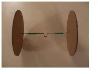
Upper Ring, Inner Ring, Flip Axle and their assemblies
Partial section view of the inner and upper rings @ Flip axle area (#2150.500E002-J)
2D detail drawing #2150.530D201-C from www.noao.edu/ets/Mechanical/
The 1st case model for the force distribution: (See page 11 for the 2nd case model). Hollow shaft supports by two (2) bearings, overhanging concentrated load P, and torsional moment Mt applying simultaneously. Where: L = 4.0 in, the center distance between two bearings (KAYDON KG047AR0) a = 7.50 in (See page 12 for the length derivation) P = 20,000 lbs. (See page 14 of report #1) Mt = 50% of the weight of the PF Cage x 1.65 x the eccentric distance* = 0.5 x 12,000 lbs x 1.65 x 6.00 in (where1.65, seismic factor) = 59,400 lbs- in Mb@R2 = Pa = 150,000 lbs –in (maximum) Mr@R2 = (Mb^2 + Mt^2)^0.5 = 161,333 lbs –in (Resultant maximum moment) R1 = 37,500 lbs. ↓ R2 = 57,500 lbs. ↑
*: assuming the distance between the gravity ctr. of the PF Cage to the axial axis of the shaft. The geometric properties of the shaft: Between two bearings section: do = 4.75 in, di = 3.00 in Across = 10.65 in^2 Ir1-r2 = 21 in^4, moment of inertia Sr1-r2 = Ir1-r2 /ro = 8.842 in^3, section of modulus Jr1-r2 = 42 in^4, polar moment of inertia Location where 7.5” away from bearing R2 (x2 = 7.50”, cantilever): do = 5.245 in, di = 3.50 in Across = ~10.24 in^2 Ix2@7.5” = ~21.33 in^4, moment of inertia Jx2@7.5” = ~50.97 in^4, polar moment of inertia Assuming: material of the shaft: AISI C1018 (cold finished steel) E = 29 x 10^3 ksi, modulus of elasticity G = 11.5 x 10^3 ksi, shear modulus of elasticity Ft = 64 ksi (tensile strength), Fy = 54 ksi (yielding strength)
The calculated deflections: ∆max@ the cantilever where load P applying (x2=7.50”) = 0.00697 in ∆max between two bearings (x1 = 2.31”) = 0.00025 in өtwist angle = Mta/JG = 0.000922 radians To find the allowable stresses VS. working stresses by two different approaches: 1st approach: To find the allowable stresses per ASD of AISC 9th edition: Fb = 0.6 Fy(1- 0.25) = 24.3 ksi Fv = 0.4 Fy (1 –0.25)= 16.2 ksi The calculated working stresses: fb = Mr@R2 / Sr1-r2 = 161,333 lbs-in / 8.842 in^3 = 18.247 ksi < Fb= 24.3 ksi (max. calculated working bending stress) fv1 = 20,000 lbs / Across= 10.65 in^2 = 1.878 ksi fv2 = Mt c / Jr1-r2 = 59,400 lbs-in x 2.375 in / 42 in^4 = 3.359 ksi fv = fv1 + fv2 = 5.237 ksi < Fv= 16.2 ksi (max. calculated working shear stress)
2rd approach: The allowable stresses per ASME code for a shaft design (Maximum shear stress theory): Fb1 = Fv1 = 0.18 Ft (1-.25) = 8.64 ksi → the lesser Fb2 = Fv2 = 0.30 Fy (1-.25) = 12.15 ksi Fb = Fv = Fb1 = Fv1 = 8.64 ksi The calculated working stress of the shaft: fb = fv = [16/ π do^3 (1-k^4)] x [(KbMr)^2 + (ktMt)^2]^0.5 = 9.716 ksi > Fb = Fv = 8.64 ksi The working stress is too large subject to the B.C.! where: k: = di/do Kb: combined shock and fatigue factor applied to the bending moment, assuming 1.0 Kt: combined shock and fatigue factor applied to the torsional moment, assuming 1.0 do, di, Mr & Mt: see page 6 and page 7 for the details.
Conclusions (under the current defined boundary condition): • The existing bearings of the shaft (KAYDON Bearing #KG047AR0) will • not meet the requirements for applying the shaft under the new design • configurations (see page 5 for the calculated results). • The existing shaft will not meet the new design criteria as it defined (the • working stress is higher than the allowable stress, see page 8 from the • 2nd approach calculations). However, to select a medium carbon, hot • rolled, more ductile steel with higher strength should fulfill such design • requirements, also the shaft design should minimize the stress concentration. • The deflection values (see page 7) will not change under the same defined • boundary condition (with the various steel materials) in general.
References: • “Flip Axle”, Report #1, by Andy Stefanik, July 23, 2008 • “Allowable Stress Design”, AISC 9th edition. • “Theory and Problems of Machine Design”, by Hall, Holowenko, Laughlin, 1961. • Section 2.10 and Table 37 of “Roark’s Formulas for Stress & Strain”, • by Warren C. Young, 6th edition. • “Ryerson Stock List”, by J.T. Ryerson & Son, Inc. 1991. • Link http://www.noao.edu/ets/Mechanical/ for the details of the related 2D fab. drawings. • See page 13 for the detail information of the KAYDON bearing #KG047AR0 & its link.
The 2nd case model for the force dist.: Hollow shaft supports by 2 bearings, overhanging uniform load m distributes over length a, torsional moment Mt apply simultaneously. Where:L = 4.0 in, the center distance between two bearings (KAYDON KG047AR0) a = 8.75 in, the contact length of the shaft where taking the uniform load m. b = 3.125”, the dist. between the ctr. of bearing R2 and the edge of the inner ring. m = 20,000 lbs./8.75 in = 2,286 lbs/in (See page 12 for the value calculations of a & b) By transferring the uniform load m to the equivalent concentrate load P, it finds that: ½ a + b = 4.375” + 3.125” = 7.50” (The overhanging dist. from R2 to the equivalent concentrated load P) The above 2nd model case becomes the same model case as on page 5: (1st case model for the force dist.) Mt = 50% of the weight of the PF Cage x 1.65 x the eccentric distance* = 0.5 x 12,000 lbs x 1.65 x 6.00 in = 59,400 lbs- in (see page 5) Mb@R2 = Pa = 150,000 lbs –in (maximum) The resultant moment Mr@R2 =(Mb^2 + Mt^2)^0.5 = 161,333 lbs –in So, we only use the model on page 5 to carry out the rest detail calculations.
The dimension derivation for force distribution model case 1 ( ref. page 5): 1. L = 5.937” – 0.937” – 2 x0.50”(between two ctr. Line of the bearings) = 4.00” (See page 4 and page13 drawing #2150.500E002) 2. a = [8.50”-6.875” (per dwg. #2150.500E036) +1.0” (gap between the inner & outer rings) + 0.50” (half width of the bearing)]+ [97.0” –(85.75” + 6.50”) (per #2150.500E020) – 0.375” (per #2150.500C027)] = 3.125” +4.375” = 7.50” The dimension derivation for force distribution model case 2 ( ref. page 11): 1. L = 5.937” – 0.937” – 2 x0.50”(between two crt. Line of the bearings)) = 4.00” (See page 4 and page13 drawing #2150.500E002) 2. b = 8.50” – 6.875” (per dwg. #2150.500E036) + 1.0” (gap between inner & outer rings) + 0.50” (half width ofthe bearing) = 3.125” 3. a = 11.625” (per page 4/#2150.530D203) – 3.125” (b) + 0.50” (1/2 width of the bearing) -0.25” (chamfersize of the shaft) = 8.75”