Download
1 / 18
180 likes | 319 Vues
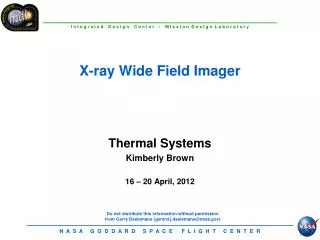
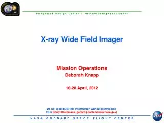
X-ray Wide Field Imager. Mechanical Sara Riall David Peters 16 – 20 April, 2012. DEPLOYED CONFIGURATION. LAUNCH CONFIGURATION. Atlas V 411 Fairing. CG calculation. CG Location. CP Calculation. CP. CG. Mechanical Design rational.

E N D
X-ray Wide Field Imager Mechanical Sara Riall David Peters 16 – 20 April, 2012
LAUNCH CONFIGURATION Atlas V 411 Fairing
CG calculation CG Location
CP Calculation CP CG
Mechanical Design rational • FMA & Instrument deck installed into “Telescope” structure (3 each) • Telescope Assembly installed into spacecraft bus
Telescope Structure Definition(metering structure) • Mass is based on configuration shown • 5.08cm wall thickness cylinder using 0.1016cm[.04”] composite skin and al aly core honeycomb panel • 2.54cm wall thickness cone using 0.1016cm{.04”] composite skin & al aly core honeycomb panel • Added 25% to the mass of the cone to accommodate mounting flanges and external stiffener ring
Bus Layout S/A (2X) OMNI(2X) RIU PROP TANK(3X) PSE BATTERY RMU DPA .5M HGA PO SUN SHADE IAU (2X) CDU(2X)
POTENTIAL SUN IMPINGEMENT ISSUE SUN MAY BE VISIBLE TO FMA AT 30 DEGREE PITCH AND 30 DEGREE ROLL (AS SHOWN) MAY NEED ADDITIONAL SUN SHIELDING IN THIS CASE
Acronym List CTE- coefficient of thermal expansion • FMA- flight mirror assembly • SMAD- space mission analysis and design • S/A –solar array • Cp-center of pressure • Cg- center of gravity • s/c –space craft • MS- mechanical structure • CCW- counterclockwise • HGA- High gain antenna • IAU- Integrated avionics unit • RIU- Remote interface unit • PO-precision unit • CDU-COMSEC decryption unit • DPA-data processing assembly • RMU- redundancy management unit
Launch Configuration (Falcon 9) Meets volume, but not 30% mass margin