Download
1 / 46
480 likes | 660 Vues
Regenerative Electric Flight Synergy and Integration of Dual-role Machines J. Philip Barnes 25 Oct 2014. Animated slides: F5 key Also: View ~ "Notes Page". Great theoreticians and experimentalists (all Ph.D.).

E N D
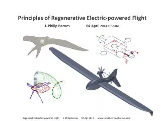
Regenerative Electric Flight Synergy and Integration of Dual-role Machines J. Philip Barnes 25 Oct 2014 Animated slides: F5 key Also: View ~ "Notes Page" Regenerative Electric-powered Flight J. Philip Barnes
Great theoreticians and experimentalists (all Ph.D.) Ludwig Prandtl - Germany Albert Betz - Germany Photo Permission requested Photo Permission requested Academy of Achievement Royal Aeronautical Society Hermann Glauert - U.K. Paul MacCready - USA Regenerative Electric-powered Flight J. Philip Barnes
Presentation Contents • Regen. elec. flight: Origin & Introduction • Dual-role machines: • Propeller and wind turbine • DC motor-generator • Brushless motor-generator • Integration: • Inverter-rectifier • DC boost converter • "Chop" Vs. "Boost" architecture • “Regenosoar” aircraft concept • Summary & Look Ahead
Regen Aircraft Elements and Operation • Windprop • Fixed rotation direction • Sign change with mode • Thrust, Torque • Power, Current Motor-Gen (M-G) Power Electronics • Energy Storage Unit: • Battery and/or: • Ultra capacitor • Flywheel w/M-G Exploit opportunities to store Vs. expend energy Regenerative Electric-powered Flight J. Philip Barnes www.HowFliesTheAlbatross.com
Presentation Contents • Regen. elec. flight: Origin & Introduction • Dual-role machines: • Propeller and wind turbine • DC motor-generator • Brushless motor-generator • Integration: • Inverter-rectifier • DC boost converter • "Chop" Vs. "Boost" architecture • “Regenosoar” aircraft concept • Summary & Look Ahead
Propeller Wake, Pitch, and Blade Angles • Wake induces downwash • (normal to local section) • Pitch: • helix length per rotation • htip = 2 p R tan btip • Uniform pitch: • r tanb = R tanbtip • Blade tip angle (btip): • 14o ~ low pitch • 30o ~ high pitch Horseshoe Vortices R r • Effect of more blades (fixed T, R): • Steep blade angle, much lower RPM • Lower tip Mach, much-reduced noise • High torque → dual & counter rotation • Numerically integrate wake for loading Blade angle (b) at radius (r) is measured from rotation plane to the chord line at (r) Regenerative Electric-powered Flight J. Philip Barnes www.HowFliesTheAlbatross.com
Test data validating Glauert's rationale on induced velocity F.E. Weick, Aircraft Propeller Design, McGraw-Hill, p. 102-103 Gradual buildup Immediate swirl, as predicted by Glauert Regenerative Electric-powered Flight J. Philip Barnes
Rotor blade velocity diagram - "Pinwheeling" condition • Propeller or wind turbine • Angle of attack = 0 • No change to flow direction • No change to relative wind • Helical drag wake (unloaded) • wr tanb= Vo (all sections) • or, r tanb= const.=R tanbtip W2 Helical wake w r Blade section Looking outboard, Blade at 3 o’clock Vo Chord line Axial wind b Pinwheeling sets up "Betz Condition" • Propeller or turbine at no load Perturb w or Vo to load rotor • Helical wake (drag and/or vortex) • Sets blade angle distribution b(r): b = tan-1 [ Vo / (wr) ] • Says nothing about blade planform Vo Relative wind W1 b Rotational wind,w r Vo J. Philip Barnes www.HowFliesTheAlbatross.com
Propeller blade - comprehensive velocity diagram • Non-rotational (axial) inflow • Axial velocity locally conserved • Finalswirl imparted suddenly • Helical wake anchored at c/4 • Wake ~ aligned with chordline • Wake-induced velocity (Vi) • Glauert: 2Viq at "rotor out" • Absolute velocity (V) increased • Relative wind (W) decreased • Immediate static pressure rise W2 Blade section Looking outboard Blade at 3 o’clock Helical wake vortex sheet w r - 2Viq V1 Chord line V2 b Axial wind Vix V1 Vo+Vix Vi Viq Glauert: consistent physics & geometry Vortex wake ~ aligned with chord line Betz cond. (wake helix), prop or turbine, with or without rotor loading, provided: r tan b= const. and z=0 (sym. sections) f Zero-lift line Rotational wind Wq w r - Viq z Relative wind W1 a V1 J. Philip Barnes www.HowFliesTheAlbatross.com
Windprop Blade Angle and Operational Mode b L b b v v v w r -L w r w w r w w • Symmetrical sections and r tanb = R tanbtip Turbine Propeller Pinwheel • Pinwheeling: Zero angle of attack, root-to-tip • - No thrust, no torque, small drag • Efficient prop: Rotate ~115% of “pinwheel RPM,” or fly at 87% of “pinwheel airspeed” • Efficient turbine: Rotate ~ 87% of “pinwheel RPM,” or fly at 115% of “pinwheel airspeed” Define: “Speed ratio,” s v / vpinwheel = v / [ wR tanbtip ] Regenerative Electric-powered Flight J. Philip Barnes www.HowFliesTheAlbatross.com
o o b b = 14 = 30 Low-RPM8 Blades, tip tip 1.0 Efficiency 0.8 c c l_min l_max Blades_btip 2_14o 8_30o 0.6 h Propeller f v / (t w) Turbine t w / (f v) 0.4 0.2 Speed Ratio, s ≡ v / (w R tan btip) 0.0 0.5 0.6 0.7 0.8 0.9 1.0 1.1 1.2 1.3 1.4 1.5 1.6 1.7 1.8 1.0 0.9 Propeller ~ climb Force Coefficient, F ≡ f/(qpR2) 0.8 High-RPM2 Blades, B=8 0.7 B=2 0.6 0.5 0.4 Propeller ~ cruise 0.3 F Sym. Sections 0.2 b b tan R r = tan tip Max efficiency 0.30 0.1 Blade Geometry Regeneration Max capacity 0.25 0.0 Regeneration Pinwheel 0.20 R Chord, c/ -0.1 0.15 F= -0.011 @ B=2 Thickness 2 -0.2 0.10 F= -0.008 @ B=8 8 hub -0.3 0.05 Speed Ratio, s≡ v / (w R tan btip) R r / -0.4 0.00 0.5 0.6 0.7 0.8 0.9 1.0 1.1 1.2 1.3 1.4 1.5 1.6 1.7 1.8 0.00 0.25 0.50 0.75 1.00 Windprop Efficiency and Thrust • Comparable efficiency by mode • Eight blades quieter than two • Climb power ~ 7x cruise power Regenerative Electric-powered Flight J. Philip Barnes www.HowFliesTheAlbatross.com
Presentation Contents • Regen. elec. flight: Origin & Introduction • Dual-role machines: • Propeller and wind turbine • DC motor-generator • Brushless motor-generator • Integration: • Inverter-rectifier • DC boost converter • "Chop" Vs. "Boost" architecture • “Regenosoar” aircraft concept • Summary & Look Ahead
Motor-generator Principles t Electromotive force, e = potential energy / charge = work / charge, (Fp / q) L = 2 N w (D/2) B L e = NDBL w ≡ k w (+) Charge (q) with velocity, V in magnetic field of strength, B: Force vector, F = q V x B L N turns k = "EMF constant" B w Fq e i i Fp Torque, t = 2N (D/2) B (dx/dt) dq = 2N (D/2) B (dq/dt) dx t = NDBiL = NDBL i = k i vi B vq E t w = e i Both modes t Motoring N turns w Fq e i i Fp vi B Change to generator mode: Same direction, rotation, w Same sign for EMF, e Sign change of torque, t Sign change of current, i vq E Generating Regenerative Electric-powered Flight J. Philip Barnes www.HowFliesTheAlbatross.com
System Motoring and Regeneration Efficiencies Typical controller pulse-width modulation (PWM) of duty cycle (d) and efficiency h ≈ d 0.25 (*) Rt System total resistance em=kw t eb w Torque Motor Regen i • "Ideal system efficiency" ignoring controller and all losses • system motor ≈ t w/(eb i) ≈ emi / (eb i) = em/ eb = k w / eb • system regen ≈ ebi / (tw) ≈ eb i / (emi) = eb / em=eb / (k w) (*) AiAA 2010-483, Lundstrom, p.8 Regenerative Electric-powered Flight J. Philip Barnes www.HowFliesTheAlbatross.com
Motor-generator & Battery ~ Performance Envelope and Data 100% Duty Cycle eb /(kw) THEO. EFFICIENCY, kw/eb CURRENT GROUP, i Rt / eb TORQUE GROUP, t Rt / (k eb) REGENERATION LMC "generator curve" 48V / 3,600 RPM k = 0.16 N-m/A Rt = 0.041 Ohm LMCLTD.net MOTORING EEMCO 427D100 24V / 15,000 RPM k = 0.015 N-m/A Rt = 0.075 Ohm Windprop synergy i t Phil Barnes Apr-08-2011 Trends match theory Regenerative Electric-powered Flight J. Philip Barnes www.HowFliesTheAlbatross.com
Presentation Contents • Regen. elec. flight: Origin & Introduction • Dual-role machines: • Propeller and wind turbine • DC motor-generator • Brushless motor-generator • Integration: • Inverter-rectifier • DC boost converter • "Chop" Vs. "Boost" architecture • “Regenosoar” aircraft concept • Summary & Look Ahead
Brushless "DC" Motor-generator ~ "Y" configuration Brushed Vs. Brushless Virtues, features, & limits Brushed: Theory foundation tw=ei ; e=kw ; t=ki 2-wire interface Simplified control Brush maintenance ~120V limit (arcing) Low-speed cogging N S Brushless: Inverter required 3-wire interface >1000V capable Minimal cogging Same as brushed: tw=ei ; e=kw ; t=ki Regenerative Electric-powered Flight J. Philip Barnes
Brushless motor-gen. & inverter: Equivalent DC machine t w = emi motor or gen Equivalent DC machine Inverter- Rectifier t M-G eb w i Brushless machine with inverter/rectifier as a system follows brushed DC machine principles: tw = emi ; em = kw ; t = k i Both systems have 2-wire interface with the power circuit Regenerative Electric-powered Flight J. Philip Barnes www.HowFliesTheAlbatross.com
Presentation Contents • Regen. elec. flight: Origin & Introduction • Dual-role machines: • Propeller and wind turbine • DC motor-generator • Brushless motor-generator • Integration: • Inverter-rectifier • DC boost converter • "Chop" Vs. "Boost" architecture • “Regenosoar” aircraft concept • Summary & Look Ahead
Transistor and flyback diode • "High-tech, high-power light switch" • Inverter commutation & DCBC boost adjust • Lo-freq. (20-100 Hz) for commutation • Hi-freq. (>10 kHz) pulse-width-mod (PWM) • VGE (say 12 V) sets the collector current IC • Collector voltage VCE(say 600 V) sets power • Flyback diode for switch energy dissipation • iGBT & diode unidirectional (via arrows) • Transistor ~ 2V loss ; Diode ~ 0.7V loss IC iGBT MOSFET VCE Collector Flyback Diode Gate VGE Emitter Gate voltage (VGE) "opens the valve" Gate voltage, VGE Gate voltage, VGE Regenerative Electric-powered Flight J. Philip Barnes
Inverter-rectifier ("inverter" for motoring mode) VB 1 1 2 2 3 3 VB • Switch pairs: one "upper" & one "lower" • Avoid short circuit: Always "diagonalize" • Each phase, per cycle: • - Connect to battery voltage 120o • - Connect to ground 120o • - "Float" twice for 60o each float • Inverter converts 2-wire DC to 3-wire "AC" • Commutation toggles each phase 0-to-VB Regenerative Electric-powered Flight J. Philip Barnes
DC-to-AC conversion ~ "inverter" commutation waveforms AC basis "Dead time" avoids short circuit Inverter Regenerative Electric-powered Flight J. Philip Barnes
Inverter-rectifier ("inverter" for motoring mode) ~ Snapshots VB VB VB VB 1 1 1 1 1 1 1 VB VB VB 1 2 2 2 2 2 2 VB 2 2 3 3 3 3 3 3 3 3 "Upper" switch pairs diagonally with a lower switch Two phases are operating; one phase is "floating" Regenerative Electric-powered Flight J. Philip Barnes
Inverter-rectifier ("rectifier" for generating mode) - iGBT Snapshot E1 - E3 > EB 1 1 2 2 EB Diodes provide "free" regen! 3 3 Current to battery! • Rectifier converts 3-wire AC to 2-wire DC • Battery is recharged via flyback diodes • Diodes enable only two phases at once • Commutation "ignored" (unidirect. iGBT) Regenerative Electric-powered Flight J. Philip Barnes
Inverter-rectifier ("rectifier" for generating mode) - MOSFET E1 - E3 > EB 1 1 2 2 3 3 EB Current to battery • Rectifier converts 3-wire AC to 2-wire DC • Charge battery via MOSFETs & flyback diodes • Bi-directional: Comm. MOSFET assists diode Regenerative Electric-powered Flight J. Philip Barnes
Pulse-width modulation: Energy loss due to "chopping" • Commutation voltage cycle ion iav • Comm. + PWM superimposed || dt | t | • At a given voltage, cruise current ≈ 15% of climb or accel current • Superimposed on commutation: PWM "chopping" at part load • Typical switching frequency (f) for chopping ≈ 20 kHz (inaudible) • Reduce the duty cycle (d) to reduce average current (iav = d ion) • Energy is lost (iGBT & diode) with each on/off switching cycle • Per-iGBT switching energy loss (Sp) ≈ 20 mJ per switch cycle • To minimize chopping losses, apply PWM only to "upper" phase • Switch power loss = f Sp = 0.4-1.0 kW = 13-05% @ 3-20 kW/phase Remove PWM from commutation; Incorporate DC boost converter Regenerative Electric-powered Flight J. Philip Barnes
Presentation Contents • Regen. elec. flight: Origin & Introduction • Dual-role machines: • Propeller and wind turbine • DC motor-generator • Brushless motor-generator • Integration: • Inverter-rectifier • DC boost converter • "Chop" Vs. "Boost" architecture • “Regenosoar” aircraft concept • Summary & Look Ahead
DC boost converter enables efficient motoring & regen VM L M-G brushed or brushless with inv. VB C iGBT PWM Boost battery voltage to efficiently drive the M-G as a motor Boost motor-generator EMF to efficiently recharge the battery • DCBC: Key enabler, efficient bi-directional power management • Only the motoring mode is shown in the introductory graphic above • “Boosts” DC voltage ~ 0-500 % with minor input/output ripple • Power conservation: doubling the voltage halves the current • Enables reduced battery totem pole length, i.e. Toyota Prius* • DC voltage gain or “boost” is controlled by PWM “duty cycle” • PWM used for DCBC gate current, not motor-gen main current Regenerative Electric-powered Flight J. Philip Barnes
DC boost converter – Equivalent circuits VM L M-G brushed or brushless with inv. VB C iGBT PWM iGBT on iGBT off iB iB VM VM iM iM L diB /dt L diB /dt C dVM/dt VB VB C dVM/dt dt |--t--| iGBT gate PWM d≡ duty cycle ; t≡ period Regenerative Electric-powered Flight J. Philip Barnes
DC boost converter – Voltage gain & conversion efficiency Time segment 1: iGBT on for Dt = dt Segment 2: iGBT off for Dt = (1-d)t [a] Voltage loop: VB - L DiB1 /(dt) = 0 [b] VB - L DiB2 /[(1-d)t] = VM iB iB VM VM [c] Output current: iM - C DVM1 /(dt) = 0 [d] iB - C DVM2 /[(1-d)t] = iM iM iM L DiB2 /[(1-d)t] L DiB1 /(dt) [e] PWM cycle: DiB1 + DiB2 = 0 [f] DVM1 + DVM2 = 0 C DVM1/(dt) C DVM2 /[(1-d)t] [g] Combine [a,b,e]: VM/VB = 1/(1-d) VB [h] via [c,d,f]: iM/iB = 1-d VB Combine [g,h]: h ≡iMVM /(iBVB) = 1 iGBT gate PWM dt |--t--| • Voltage gain is set by duty cycle (d) • Efficiency = 1 (resistance neglected) d≡ duty cycle ; t≡ period Regenerative Electric-powered Flight J. Philip Barnes
DC boost converter - efficiency and regen application 233 Vdc in Regen Cruise Climb Regen 5 10 15 20 kW Motor "Evaluation of 2004 Toyota Prius," Oakridge National Lab, U.S. Dept. of Energy L VB M-G C iGBT PWM • DC boost converter integrates windprop and motor-generator • Adjust PWM duty cycle to hold voltage gain as RPM decreases • Efficient bi-directional power over a wide operating range Regenerative Electric-powered Flight J. Philip Barnes
Voltage Map - Motoring and Regen with DC boost converter Batt, boost factor 3.0 Voltage Climb Batt: 600V M-G: 400V M-G, boost = 2.0 M-G, boost = 1.5 Batt, boost factor 2.0 Cruise Max Regen M-G: 260V Batt: 200V Motor-gen EMF, no boost Opt. Regen Battery, no boost • Boost the battery for motoring • Boost the M-G for regeneration %RPM Regenerative Electric-powered Flight J. Philip Barnes
Presentation Contents • Regen. elec. flight: Origin & Introduction • Dual-role machines: • Propeller and wind turbine • DC motor-generator • Brushless motor-generator • Integration: • Inverter-rectifier • DC boost converter • "Chop" Vs. "Boost" architecture • “Regenosoar” aircraft concept • Summary & Look Ahead
Architectures compared i Inverter- Rectifier eb M-G PWM superimposed on commutation "Chopper" architecture PWM main current chop Cruise: high chopping loss Regen: none or inefficient PWM w w t t Commutation 12V i Inverter- Rectifier DC Boost Converter 2-way boost eb M-G "Boost" architecture PWM sets DCBC boost Efficient motor & regen Regenerative Electric-powered Flight J. Philip Barnes www.HowFliesTheAlbatross.com
Presentation Contents • Regen. elec. flight: Origin & Introduction • Dual-role machines: • Propeller and wind turbine • DC motor-generator • Brushless motor-generator • Integration: • Inverter-rectifier • DC boost converter • "Chop" Vs. "Boost" architecture • “Regenosoar” aircraft concept • Summary & Look Ahead
Regenosoar - Features and Design Rationale Regen parked in the wind With safety perimeter Counter rotors Symmetric flow Zero net torque 8-blade rotors Low RPM, quiet, Low vibration Low tip Mach Ground handling No assistance req'd Winglet tip wheels Pod-air-cooled MG & PE Compact power train Battery, motor-gen and powertrain Pusher Config. Symmetry upstream Max. laminar flow Regenerative Electric-powered Flight J. Philip Barnes
Min. Sink Section Windprop System Removed Max L/D Section and Vehicle Drag Polars "Clean configuration" ~ Windprop System Removed 1.50 Lift Coefficient, c or c L l 1.25 1.00 "Clean" aircraft 0.75 0.50 0.25 Drag Coefficient, c or c D d 0.00 0.00 0.01 0.02 0.03 0.04 0.05 Regenerative Electric-powered Flight J. Philip Barnes www.HowFliesTheAlbatross.com
Steady-state load factor (nn) ~ “g-load” and turn radius L= nn w v nn L/ w = cosg / cosf * Glide: nn 1 Turn: nn 1 / cosf f g * SAE 2004-01-3088 EQN 5.2, dg/dt = 0 w Load Factor and Bank Angle Load Factor and Turn Radius 400 1.05 50 350 n Bank Angle Turn Radius, m n 300 fo 40 1.1 250 r = v2(cosg) / (g tanf) 30 200 1.2 f = cos-1[(cosg)/nn)] Thermaling 150 20 1.4 1.6 100 10 50 Load Factor, nn Airspeed, v_km/h 0 0 0 20 40 60 80 100 120 140 1.0 1.1 1.2 1.3 1.4 1.5 1.6 Regenerative Electric-powered Flight J. Philip Barnes www.HowFliesTheAlbatross.com
Load Factor and “Clean” Sink Rate 0.0 dz/dt ~m/s Sea level Max L/D 2 25 kg / m Min Sink A = 16 -0.5 1.0 -1.0 1.2 1.4 -1.5 1.6 g-Load, nn -2.0 Airspeed, v ~ km/h -2.5 50 60 70 80 90 100 110 120 130 140 150 cL= nn w / (qs) “Clean” REGEN Windprop removed Regenerative Electric-powered Flight J. Philip Barnes www.HowFliesTheAlbatross.com
Steady-state climb or descent ~ New Formulation, New Insight Derive steady-climb Equation f v L= nn w T-D g g w Note:nn= cosg /cosf * cL= nn w / (qs) • Glider, soaring bird, or "clean" regen • T/D=0 (no thrust) • Sink rate (-dz/dt) = nn(D/L)v • With or without propulsion system • Sink increases with g-load (nn) • D/L also increases with (nn) • Sink increases with airspeed (v) • Regen operating mode T/D • climb 6.3 • cruise = 1.0 • pinwheel glide -0.1 • efficient regen (thermal) -0.4 • capacity regen (descent) -1.0 * SAE 2004-01-3088 EQN 5.2, dg/dt = 0 Regenerative Electric-powered Flight J. Philip Barnes www.HowFliesTheAlbatross.com
Regenerative Electric Flight Equation and Implications • Regen must have • Updraft • High L/D, Low sink • High efficiency • Prop & turbine • Energy storage “Clean” sink rate Windprop Effect Updraft • e ≡ “Exchange Ratio,” as applicable: • turbine system efficiency ~71% • 1 / propeller system efficiency • 0 for pinwheeling (no exchange) “Total Climb” “Total Sink”
Thermal Updraft Contours Elevation, zo ~ m • 1oC warmer-air column • 20-minute lifetime • ~ solar power x 10 U ~ m/s 1 2 3 Total Energy = Kinetic + Potential 4 Total Energy = Kinetic + Potential + Stored Regenerative Electric-powered Flight J. Philip Barnes www.HowFliesTheAlbatross.com
Climb and Regeneration in the Thermal (minimum-sink airspeed) Elevation, m Elevation, m Climb rate Contours Energy rate Contours Optimum Elevation, m Equilibrium Regeneration Regenerative Electric-powered Flight J. Philip Barnes www.HowFliesTheAlbatross.com
Regenerative Electric Flight Equation Applied for RegenoSoar 0.82 0.88 Regenerative Electric-powered Flight J. Philip Barnes www.HowFliesTheAlbatross.com
Presentation Contents • Regen. elec. flight: Origin & Introduction • Dual-role machines: • Propeller and wind turbine • DC motor-generator • Brushless motor-generator • Integration: • Inverter-rectifier • DC boost converter • "Chop" Vs. "Boost" architecture • “Regenosoar” aircraft concept • Summary & Look Ahead
Regenerative Electric-powered Flight • Windprop: 8 blades spin slow, quiet, & efficient • DC & BLDC machines: EMF proportional to RPM • M-G & battery verify theoretical efficiency trends • Synergy of windprop & MG: Efficiency Vs. RPM - Optimum “speed ratios” ~ 85% & 115% by mode • Popular "chopper" control: inefficient at cruise • DC boost converter: efficient climb, cruise, regen • Regen applications: • Thermal, ridge, wave, final descent, .... • UAV fleet, storm rider, earth observer, .... • Give up 2% prop efficiency w/symmetric sections to gain perhaps 5-15% range and/or flying time VM M-G iGBT A "regen" is coming soon to an airport near you! Regenerative Electric-powered Flight J. Philip Barnes www.HowFliesTheAlbatross.com