Download

1 / 16
200 likes | 443 Vues
A Lossless, Accurate, Self-Calibrating Current-Sensing Technique for DC-DC Converters. H. Pooya Forghani-zadeh and Prof. Gabriel Rincón-Mora Georgia Tech Analog and Power IC Lab Department of Electrical and Computer Engineering Georgia Institute of Technology November 2005. Introduction.

E N D
A Lossless, Accurate, Self-Calibrating Current-Sensing Technique for DC-DC Converters H. Pooya Forghani-zadeh and Prof. Gabriel Rincón-Mora Georgia Tech Analog and Power IC Lab Department of Electrical and Computer Engineering Georgia Institute of Technology November 2005
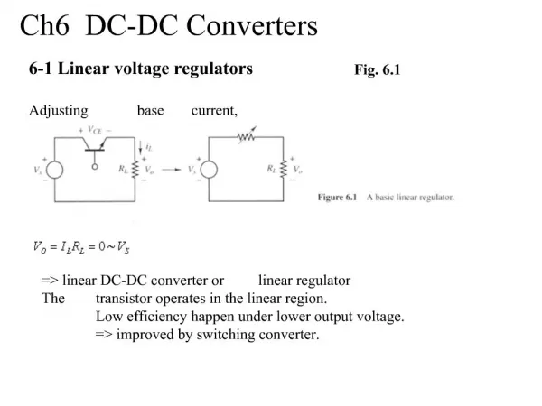
Introduction Buck (step-down) converter Vin M1 Vo L ILoad C D1 Controller Current-sensing applications: IL=? • Overload protection • Current-mode controller • Current sharing • Mode-hoping for high efficiency • Inductor multiplier and … Current-sensing requirements: • Lossless • Accurate • Continuous • Low noise • Integrable-> DC-DC converter ICs Goal: Lossless and accurate current sensing for high performance converter ICs Intersil IPM6220A
Available Techniques-1 • Sense-FET • VSFET=RSFETIL/ N • Problems: 1. On-chip switches only 2.Accuracy=±20% • MOSFET-RDS • Vds=RswIL • Problem: Low accuracy (±75% ) • Rsense • Vsense =RsenseIL • Problem: High power dissipation 4-8% loss Vin Vsense W/L=aN W/L=a Vds Rsense L RESR Vo M2 M1 VSFET RESR_C IL ILoad Iripple RSFET D1 C PWM Controller
Available Techniques-2 Filter technique: A + Voltage across inductor: VL=(RESR+sL)IL - VSense Rf Cf Vin Voltage across Cf: RESR L Vo RESR_C IL Iripple ILoad C if Controller Problem: The values of L and RESR are not generally known to IC designer. Even if they are known ±28% because of tolerances and temperature variation (70°C range). Available lossless techniques are not accurate without the knowledge of off-chip elements such as power MOSFET and inductor and therefore are not suitable for integration.
Proposed Technique Block Diagram Vsense CS Filter gm1 + + VL - - R2 C IL If (L/RESR)=(CR2) Control Logic Tuning & Calibration Active in Startup • The filter is used to imitate the inductor behavior. • Tuning and calibration units are added to measure off-chip elements (inductor) during the startup to increase the accuracy for unknown inductor. (CSF gain condition V/A) (1) (2) (BW condition)
Start-Up Sequence Controller The technique is suitable for integrated implementations Inductor selection Measurements & Adjustments Normal Operation Design PCB IC designer End user
Filter Adjustment Σ Inductor vL 1 AC Iref RESR (1+sL/RESR) 1/RCS Tuning the BW CSF Vrefsin(ω1t) + + Phase R2 (1) Vsense=Asin(ω1t+φ) ω1 in the order of RESR/L - Phase - Inductor vL 2 DC Iref Vref RESR 1/RCS (2) CSF + + Calibrating the Gain gm1 DC Test Signal Σ - - Vsense
On-Board Inductor Measurement • During startup, power switches (M1 and M2) are turned off, and Ma and Mb are turned on. • A current can be injected into the inductor from Vp node.
Circuit Design:Adjustable Gm-C Filter • R2 is replaced by gm2 • Transconductance is a function of bias current (BJT stage, gm=I/VT) • Resistor divider is for linearity and rail to-rail operation • Op1 buffer is to remove loading effects of divider resistors
Circuit Design: Tuning Goal: • Gm2 sweeps from minimum to maximum until count “Stop” goes from low to high • Preamplifier to enhance signal level • Cdecouple to remove dc components • k=20 • Clock frequency 300Hz
Circuit Design: Calibration Goal: • Gm1 sweeps from minimum to maximum until count “Stop” goes from lowto high • Preamplifier to enhance signal level • k=20 • Iref=50mA Complete circuit uses a chopper stabilized technique to achieve low-offset operation (Figure 7.b in the paper)
Experimental Results-1 ΔI=200mA ΔI=280mA ΔI=266mA ΔI=200mA (b) Iload=0.1A(DCM) (a) Iload=0.032A (DCM) ΔI=320mA ΔI=320mA ΔI=333mA ΔI=333mA (d) Iload=1A (CCM) (c) Iload=0.5A (CCM) Estimated AC Current vs. Actual AC Current (<5% error) Proposed Proposed Rsense` Rsense` Proposed Proposed Rsense` Rsense` • 1. Output voltage ripple α ΔI (ESR=0.15Ohm, measured with 4092 Agilent) • 2. Proposed system output (estimated current)
Experimental Results-2 Ideal Curve versus Estimated Curve 0.6 6.4% 0.5 0.4 18% 0.3 Estimated Current (V) 18mV 0.2 Ibias=Ideal 0.1 Ibias=Cal for 0.5V/A gain 0 0 0.2 0.4 0.6 0.8 1 Actual Current (A) Error due to nonlinearity of gm cells (systematic offset) Transconductance not constant through whole input voltage range
Conclusions • Available lossless current-sensing techniques are not accurate without knowledge of passive components not known to IC designers. • The proposed approach enhances the accuracy of filter technique by introducing tuning and calibration at startup. • A prototype was implemented using discrete elements to verify the concept. Accuracy of 6.4% for dc portion of current (high loads) and less than 5% for ripple current is achieved. • Complete integrated circuit design of the proposed technique is in progress.
Discussion:Error Sources • This effect is considered in combination with RESRversus temperature • Predictability means how an IC-designer can predict and compensate the error source at • the design time
Comparison of Available Techniques Lossless techniques are not accurate, and accurate techniques are not lossless. [1] H. P. Forghani-zadeh, “Current-sensing techniques for DC-DC converters,” 2002.