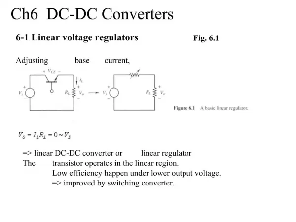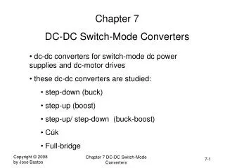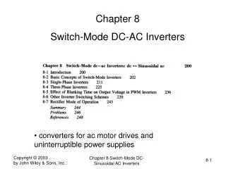
DC-DC Switch-Mode Converters
DC-DC Switch-Mode Converters. Applications : Regulated switch mode dc power supplies dc motor drives dc-dc Converters : Step-down (buck) converter Step-up (boost) converter Step-down/step-up (buck-boost) converter Cuk converter Full-bridge converter.


DC-DC Switch-Mode Converters
E N D
Presentation Transcript
DC-DC Switch-Mode Converters Applications: • Regulated switch mode dc power supplies • dc motor drives dc-dc Converters: • Step-down (buck) converter • Step-up (boost) converter • Step-down/step-up (buck-boost) converter • Cuk converter • Full-bridge converter
Functional Block Diagram of DC-DC Converter System Controlled dc output at a desired voltage level Unregulated dc voltage obtained by rectifying the line voltage, and therefore will fluctuate with line voltage magnitude
Control of DC-DC Converters In a dc-dc converter: • Average output dc voltage must be controlled to equal a desired level. • Utilizes one or more switches to transform dc from one level to another. • The average output voltage is controlled by controlling the switch on and off durations (tonand toff). • Let’s consider the following switch-mode dc-dc converter: • Average output dc voltage Vo depends on tonand toff. • Switching is done at a constant frequency with switching time period Ts. • This method is called pulse-width modulation (PWM) in which the duty ratio D is varied to control Vo, where D=ton/Ts
Control of DC-DC Converters (cont’d) • The switch control signal, which controls the on and off states of the switch, is generated by comparing a signal level control voltage vcontrolwith a repetitive waveform. • The switching frequency is the frequency of the sawtooth waveform with a constant peak. • The duty ratio D can be expressed as
Step-Down (Buck) Converter • converts dc from one level to another • the average output voltage is controlled by the ON-OFF switch • pulse-width modulation (PWM) switching is employed • lower average output voltage than the dc input voltage Vddepending on the duty ratio, D • D=ton/Ts • Average output: Applications: • regulated switch mode dc power supplies • dc motor drives • low-pass filter: to reduce output voltage fluctuations • diode is reversed biased during ON period, input provides energy to the load and to the inductor • energy is transferred to the load from the inductor during switch OFF period • in the steady-state, average inductor voltage is zero • in the steady-state, average capacitor current is zero
Step-Down (Buck) Converter: Continuous current conduction mode • Inductor current iL flows continuously • Average inductor voltage over a time period must be zero Assuming a lossless circuit Buck converter is like a dc transformer where the turns ratio can be controlled electronically in a range of 0-1 by controlling D of the switch
Example….. For a buck converter, R=1 ohm, Vd=40 V, V0=5 V, fs=4 kHz. Find the duty ratio and “on” time of the switch.
Solution…. D = V0 /Vd = 5/40 = 0.125 = 12.5% Ts = 1/fs = 0.25 ms = 250 ms Ton = DTs = 31.25 ms Toff = Ts – ton = 218.75 ms When the switch is “on”: VL = Vd - V0 = 35 V When the switch is “off”: VL = -V0 = - 5 V I0 = IL = V0 / R = 5 A Id = D I0 = 0.625 A
Step-Up (Boost) Converter • Output voltage always higher than the input voltage • When the switch is ON: diode is reversed biased output circuit is thus isolated inductor is charged • When the switch is OFF: the output stage received energy from the inductor as well as from the input • Filter capacitor is very large to ensure constant output voltage Applications: • regulated switch mode power supplies • Regenerative braking of dc motors
Step-Up (Boost) Converter: Continuous current conduction mode • Inductor current iL flows continuously • Average inductor voltage over a time period must be zero Dividing both side by Ts Assuming a lossless circuit
Step-Up (Boost) Converter: Effect of parasitic elements • Parasitic elements are due to the losses associated with the inductor, capacitor, switch and diode • Figure shows the effect of the parasitic elements on the voltage transfer ratio • Unlike ideal characteristics, in practice, Vo /Vd declines as duty ratio approaches unity
Step-Down/Step-Up (Buck-Boost) Converter • This converter can be obtained by the cascade connection of two converters: the step-down converter and the step-up converter • The output voltage can be higher or lower than the input voltage • Used in regulated dc power supplies where a negative polarity output may be desired with respect to the common terminal of the input voltage • The output to input voltage conversion ratio • This allows V0 to be higher or lower than Vd • When the switch is ON: diode is reversed biased output circuit is thus isolated inductor is charged • When the switch is OFF: the output stage received energy from the inductor
Buck-Boost Converter: Continuous current conduction mode • Inductor current iL flows continuously • Average inductor voltage over a time period must be zero Assuming a lossless circuit • Depending on the duty ratio, the output voltage can be either higher or lower than the input
Buck-Boost Converter: Effect of parasitic elements • Parasitic elements are due to the losses associated with the inductor, capacitor, switch and diode • Parasitic elements have significant impact on the voltage transfer ratio
Cuk DC-DC Converter • Named after its inventor • The output voltage can be higher or lower than the input voltage • Providesa negative polarity output voltage with respect to the common terminal of the input voltage • C1acts as the primary means of storing and transferring energy from the input to the output • In the steady-state, average inductor voltages, VL1 and VL2 are zero, therefore, VC1= Vd + V0
Cuk DC-DC Converter • When the switch is OFF: - iL1 and iL2 flow through the diode - C1 is charged through the diode by energy from both the input and L1 - energy stored in L2 feeds the output • When the switch is ON: - Vc1reverse biases the diode - iL1 and iL2 flow through the switch - since Vc1>V0, C1 discharges through the switch, transferring energy to the output and L2 - Therefore, iL2increases - Input feeds energy to L1causing iL1 to increase
Steady-state current and voltage equations…………..Cuk Vc1is constant and average voltages across L1 and L2 over a time period must be zero Equating the above two equations,
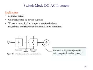
id Ia io Vd La + + voi vo= Vo - ea - Example 1: Step-down (Buck) converter The chopper below controls a dc machine with an armature inductance La = 0.2 mH. The armature resistance can be neglected. The armature current is 5 A. fs = 30 kHz. D = 0.8 • The output voltage, Vo, equals 200V. • Calculate the input voltage, Vd • Find the ripple in the armature current. • Calculate the maximum and the minimum value of the armature current • Sketch the armature current, ia(t), and the dc current, id(t).
Example 2: Step-down (Buck) converter characteristics A step-down dc-dc converter shown in the following figure is to be analyzed. The input voltage Vd = 48 V. The output filter inductance L = 0.1 mH Series resistor (with L) R = 0.2 Ω Assume in all calculations constant voltage over the series resistor R. The output capacitor C is large; assume no ripple in the output voltage. Rated output is 20 V and 25 A (a) Calculate rated output power. (b) Calculate equivalent load resistance. (c) Calculate duty ratio D for rated output. The voltage across the series resistor R must be taken into consideration.
Example 3: Step-up (Boost) converter characteristics A step-up dc-dc converter shown in the following figure is to be analyzed. The input voltage Vd = 14 V. The output voltage V0 = 42 V. Inductor L = 10 mH Output resistor R = 1 Ω Switching frequency fs=10 kHz (a) Duty ratio, switch on and off time. (b) Plot inductor and diode voltages.
Example 7-3: Cuk Converter • The above Cuk converter is operating at 50 Hz, L1=L2=1 mH and C1=5 mF • The output capacitor is sufficiently large to yield constant voltage • Vd=10 V and the output V0 is regulated to be constant at 5 V • It is supplying 5 W to a load -------------------------------------------------------------------------------------------------------- • Calculate the percentage errors in assuming a constant voltage across C1 or in assuming constant currents iL1 and iL2.
Full-Bridge dc-dc Converter • Four-quadrant operation: magnitude and direction of both v0 and i0 can be controlled • This converter consists of two legs, A and B. Each leg consists of two switches and their antiparallel diodes • A reversible flow of power is made possible by connecting diodes in antiparallel with switches • Applications: dc motor drives and dc-to-ac conversion
One of the two switches in each leg is ON • The output current io will flow continuously • (TA+ , TB-) and (TA- , TB+) are treated as two switch pairs: switches in each pair are turned ON and OFF simultaneously • vAN=Vd (if TA+ is ON and TA- is OFF) :: output current will flow through TA+ if io is positive or it will flow through DA+ if io is negative • vAN=0 (if TA- is ON and TA+ is OFF) :: output current will flow through TA- if io is negative or it will flow through DA- if io is positive • The average output voltage of the converter leg A: where ton and toff are the ON and OFF intervals of TA+, respectively. Output voltage is independent of the direction of io
Similar arguments apply to the converter leg B. • VBNdepends on Vdand the duty ratio of the switch TB+: • VBN is independent of the direction of io • Output voltage V0 (=VAN-VBN) can be controlled by controlling the switch duty ratios
(TA+ , TB-) and (TA- , TB+) are two switch pairs: one of the two switch pairs is always ON • Switching signal is generated by comparing a switching-frequency triangular wave with a control voltage • If vcontrol>vtri: TA+ and TB- are ON • If vcontrol<vtri: TA- and TB+are ON
Comparison of Converters • Buck converter: step-down, has one switch, simple, high efficiency greater than 90%, provides one polarity output voltage and unidirectional output current • Boost converter: step-down, has one switch, simple, high efficiency, provides one polarity output voltage and unidirectional output current, requires a larger filter capacitor and a larger inductor than those of a buck converter • Buck-boost converter: step-up/step-down, has one switch, simple, high efficiency, provides output voltage polarity reversal • Cuk converter: step-up/step-down, has one switch, simple, high efficiency, provides output voltage polarity reversal, additional capacitor and inductor needed • Full-bridge converter: four-quadrant operation, has multiple switches, can be used in regenerative braking
Conclusions • In many industrial applications, it is required to convert fixed dc voltage into variable dc voltage • Various types of dc-to-dc converters • Operation of dc-to-dc converters • The step-down, step-up, buck-boost and Cuk converters are only capable of transferring energy only in one direction • A full-bridge converter is capable of a bidirectional power flow • Like ac transformers, dc converters can be used to step-up or step-down a dc voltage source • Applications: electric automobiles, trolley cars, marine hoists, mine haulers, etc. • Also used in regenerative braking of dc motors to return energy back into the supply –energy savings for transportation systems with frequent stops