Chapter 8 Switch-Mode DC-AC Inverters
460 likes | 1.05k Vues
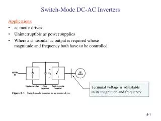
Chapter 8 Switch-Mode DC-AC Inverters. converters for ac motor drives and uninterruptible power supplies. Switch-Mode DC-AC Inverter. Block diagram of a motor drive where the power flow is unidirectional. Switch-Mode DC-AC Inverter.

Chapter 8 Switch-Mode DC-AC Inverters
E N D
Presentation Transcript
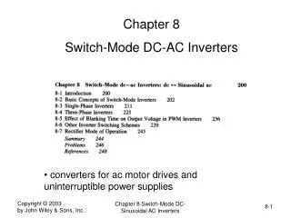
Chapter 8 Switch-Mode DC-AC Inverters • converters for ac motor drives and uninterruptible power supplies Chapter 8 Switch-Mode DC- Sinusoidal AC Inverters
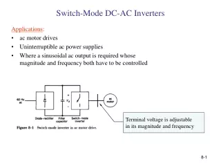
Switch-Mode DC-AC Inverter • Block diagram of a motor drive where the power flow is unidirectional Chapter 8 Switch-Mode DC- Sinusoidal AC Inverters
Switch-Mode DC-AC Inverter • Block diagram of a motor drive where the power flow can be bi-directional Chapter 8 Switch-Mode DC- Sinusoidal AC Inverters
Switch-Mode DC-AC Inverter • Four quadrants of operation Chapter 8 Switch-Mode DC- Sinusoidal AC Inverters
One Leg of a Switch-Mode DC-AC Inverter • The mid-point shown is fictitious Chapter 8 Switch-Mode DC- Sinusoidal AC Inverters
Synthesis of a Sinusoidal Output by PWM Chapter 8 Switch-Mode DC- Sinusoidal AC Inverters
Details of a Switching Time Period • Control voltage can be assumed constant during a switching time-period Chapter 8 Switch-Mode DC- Sinusoidal AC Inverters
Harmonics in the DC-AC Inverter Output Voltage • Harmonics appear around the carrier frequency and its multiples Chapter 8 Switch-Mode DC- Sinusoidal AC Inverters
Harmonics due to Over-modulation • These are harmonics of the fundamental frequency Chapter 8 Switch-Mode DC- Sinusoidal AC Inverters
Output voltage Fundamental as a Function of the Modulation Index • Shows the linear and the over-modulation regions; square-wave operation in the limit Chapter 8 Switch-Mode DC- Sinusoidal AC Inverters
Square-Wave Mode of Operation • Harmonics are of the fundamental frequency Chapter 8 Switch-Mode DC- Sinusoidal AC Inverters
Half-Bridge Inverter • Capacitors provide the mid-point Chapter 8 Switch-Mode DC- Sinusoidal AC Inverters
Single-Phase Full-Bridge DC-AC Inverter • Consists of two inverter legs Chapter 8 Switch-Mode DC- Sinusoidal AC Inverters
PWM to Synthesize Sinusoidal Output • The dotted curve is the desired output; also the fundamental frequency Chapter 8 Switch-Mode DC- Sinusoidal AC Inverters
Analysis assuming Fictitious Filters • Small fictitious filters eliminate the switching-frequency related ripple Chapter 8 Switch-Mode DC- Sinusoidal AC Inverters
DC-Side Current • Bi-Polar Voltage switching Chapter 8 Switch-Mode DC- Sinusoidal AC Inverters
Output Waveforms: Uni-polar Voltage Switching • Harmonic components around the switching frequency are absent Chapter 8 Switch-Mode DC- Sinusoidal AC Inverters
DC-Side Current in a Single-Phase Inverter • Uni-polar voltage switching Chapter 8 Switch-Mode DC- Sinusoidal AC Inverters
Sinusoidal Synthesis by Voltage Shift • Phase shift allows voltage cancellation to synthesize a 1-Phase sinusoidal output Chapter 8 Switch-Mode DC- Sinusoidal AC Inverters
Single-Phase Inverter • Analysis at the fundamental frequency Chapter 8 Switch-Mode DC- Sinusoidal AC Inverters
Square-Wave and PWM Operation • PWM results in much smaller ripple current Chapter 8 Switch-Mode DC- Sinusoidal AC Inverters
Push-Pull Inverter • Low Voltage to higher output using square-wave operation Chapter 8 Switch-Mode DC- Sinusoidal AC Inverters
Three-Phase Inverter • Three inverter legs; capacitor mid-point is fictitious Chapter 8 Switch-Mode DC- Sinusoidal AC Inverters
Three-Phase PWM Waveforms Chapter 8 Switch-Mode DC- Sinusoidal AC Inverters
Three-Phase Inverter Harmonics Chapter 8 Switch-Mode DC- Sinusoidal AC Inverters
Three-Phase Inverter Output • Linear and over-modulation ranges Chapter 8 Switch-Mode DC- Sinusoidal AC Inverters
Three-Phase Inverter: Square-Wave Mode • Harmonics are of the fundamental frequency Chapter 8 Switch-Mode DC- Sinusoidal AC Inverters
Three-Phase Inverter: Fundamental Frequency • Analysis at the fundamental frequency can be done using phasors Chapter 8 Switch-Mode DC- Sinusoidal AC Inverters
Square-Wave and PWM Operation • PWM results in much smaller ripple current Chapter 8 Switch-Mode DC- Sinusoidal AC Inverters
DC-Side Current in a Three-Phase Inverter • The current consists of a dc component and the switching-frequency related harmonics Chapter 8 Switch-Mode DC- Sinusoidal AC Inverters
Square-Wave Operation • devices conducting are indicated Chapter 8 Switch-Mode DC- Sinusoidal AC Inverters
PWM Operation • devices conducting are indicated Chapter 8 Switch-Mode DC- Sinusoidal AC Inverters
Short-Circuit States in PWM Operation • top group or the bottom group results in short circuiting three terminals Chapter 8 Switch-Mode DC- Sinusoidal AC Inverters
Effect of Blanking Time • Results in nonlinearity Chapter 8 Switch-Mode DC- Sinusoidal AC Inverters
Effect of Blanking Time • Voltage jump when the current reverses direction Chapter 8 Switch-Mode DC- Sinusoidal AC Inverters
Effect of Blanking Time • Effect on the output voltage Chapter 8 Switch-Mode DC- Sinusoidal AC Inverters
Programmed Harmonic Elimination • Angles based on the desired output Chapter 8 Switch-Mode DC- Sinusoidal AC Inverters
Tolerance-Band Current Control • Results in a variable frequency operation Chapter 8 Switch-Mode DC- Sinusoidal AC Inverters
Fixed-Frequency Operation • Better control is possible using dq analysis Chapter 8 Switch-Mode DC- Sinusoidal AC Inverters
Transition from Inverter to Rectifier Mode • Can analyze based on the fundamental-frequency components Chapter 8 Switch-Mode DC- Sinusoidal AC Inverters
Summary of DC-AC Inverters • Functional representation in a block-diagram form Chapter 8 Switch-Mode DC- Sinusoidal AC Inverters