Fluid Power Symbols
630 likes | 1.39k Vues
Fluid Power Symbols. Symbol Groups. Circles/Semi Circles. Rectangles and Squares. Diamonds. Circles/Semi-Circles. Circles generally represent devices that can deliver or use oil. Unidirectional Fixed Displacement Hydraulic Pump. Bi-directional Fixed Displacement Hydraulic Pump.

Fluid Power Symbols
E N D
Presentation Transcript
Symbol Groups Circles/Semi Circles Rectangles and Squares Diamonds
Circles/Semi-Circles Circles generally represent devices that can deliver or use oil. Unidirectional Fixed Displacement Hydraulic Pump Bi-directional Fixed Displacement Hydraulic Pump Bi-directional Fixed Displacement Hydraulic Motor Unidirectional Variable Displacement Hydraulic Pump Semi Rotary Actuator
Three Types of Pump Gear Pump Vane Pump Piston Pump Notice that the symbol does not describe the component construction. Symbols describe component functions only.
Diamonds Symbols in diamonds condition the oil in some way. Heating, cooling, filtering etc. Filter Cooler Heater
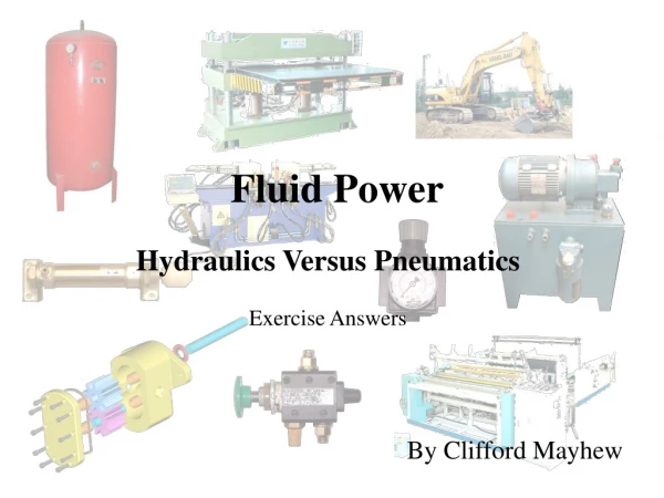
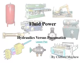
The Hydraulic Power Pack and Symbols The power pack produces the flow of oil (and consequently the pressure) for the hydraulic system. M Electric Motor Pump Tank Filter
Rectangles and Squares Rectangles and squares are generally used to represent components that direct and control oil in some way. Valves can be: One Position Two Position Three Position Usually control. Relieving or controlling pressure and flow for example. Directing the flow of oil to various positions.
Direction Arrows Arrows Can Indicate: Flow in One Direction Flow in Two Directions Rotation Variability Arrow at 30 or 60 degrees through a component that can be varied.
Valves Ports Valves Can Have Various Ports: Two Ports Three Ports Four Ports Blocked Port
Valve Classification Valves Can Commonly be Classified as: Two Port/Two Position Directional Control Valve (2/2 DCV) 2/2 Wegeventil Sperr Ruhestellung Three Port/Two Position Directional Control Valve (3/2 DCV) 3/2 Wegeventil Sperr Ruhestellung Four Port/Two Position Directional Control Valve (4/2 DCV) 4/2 Wegeventil Four Port/Three Position Directional Control Valve (4/3 DCV) 4/3 Wegeventil
The 4/3 DCV Symbol Bosch Solenoid Operated 4/3 DCV 4/3 DCV Cut Away Valve Body Solenoid Solenoid Coil Spool (Schieber)
Various 4/3 Centre Configurations Semi Open Centre (Pump Side) Semi Open Centre System Side) All Blocked Y h H
Symbol Operation Imagine the symbol moving from right to left as the valve is operated. The system connections stay in position. The symbol represents the spool position of the valve.
Valve Actuators The Valve Actuator Moves the Spool to its Various Positions: Pilot (Oil Pressure) Lever Spring Roller Push Button Solenoid
Actuators Actuators Can Be: Linear, Single Acting Linear, Double Acting Oil pressure extends the cylinder. The load retracts the cylinder. Oil pressure extends the cylinder and retracts the cylinder. Or Rotary
Variability Cylinder Cushioning Annular End Piston Rod Full Bore End Cushion Symbol Cushion Illustration The cushion slows the cylinder down just before it hits the back (or front) of the cylinder.
Other Common Components Spring Restrictor Check Valve Used to return some valve spools to a known position. Used to control the flow of oil. Allows oil in one direction only.
Control Valves Control Valves Control Pressure and Flow Relief Valve Pressure Reducing Valve Restrictor With Check Valve Pressure Relief Valves are primarily used to set the maximum system pressure. Pressure Reducing Valves are used to set the maximum system pressure at the valve outlet. The valve gives a controlled pressure output lower than the inlet pressure. Restrictors are used to control oil flow and thus actuator and system speeds. Pressure Controlling Valves Flow Controlling Valve
Relief Valve Symbol Operation Low Pressure High Pressure
Inside the Relief Valve and Restrictor Relief Valves Restrictor with Check Valve Inlet/Outlet Adjustment Inlet Outlet Adjustment Spring Inlet/Outlet Check Valve Restrictor Orifice
Test 4/2 Roller/Spring DCV 2/2 DCV 3/2 DCV 4/3 DCV