Acoustic Test Setup at South Pole: IceCube Collaboration Meeting Insights (March 2005)
140 likes | 245 Vues
This document outlines the motivation and evaluation for acoustic detection in the South Polar ice during the IceCube Collaboration Meeting in Berkeley, March 2005. It discusses key acoustic parameters, including absorption length, sound speed, and noise levels, essential for detecting transient events. The proposed setup utilizes IceCube's infrastructure with underwater sensor modules, transmitters, and auxiliary devices optimized for low temperatures. The text details the design considerations, cable specifications, and deployment strategies aimed at minimizing signal interference while maximizing detection capabilities.

Acoustic Test Setup at South Pole: IceCube Collaboration Meeting Insights (March 2005)
E N D
Presentation Transcript
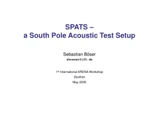
Acoustic test setup at south pole IceCube Collaboration Meeting, Berkeley, March 2005
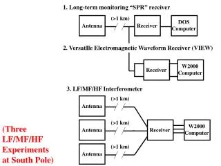
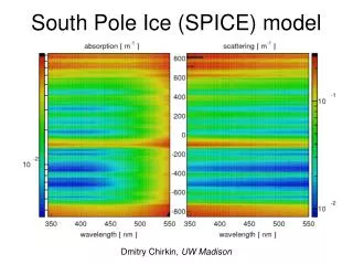
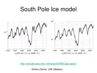
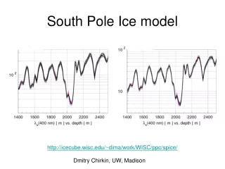
Motivation Evalution of acoustic detection needs acoustic parameters of south polar ice • Absorption length • ≈ few km • temperature dependant depth dependant • Speed of sound / refraction • vice≫ vwater larger signals ( Pmax∞ vice2) • density dependant refraction of surface noise • Noise level • determines energy threshold • Background events • few signal events/year few transient events or good suppression
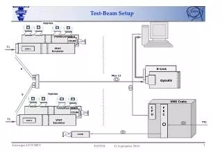
Setup • Use IceCube • 3 distant holes • down to 400 m • 7 levels per hole • sensors • transmitters • auxiliary • Surface digitization • String PCs • DAQ • Power • Fiber LAN
Acoustic stage • In all three holes • at the same height do measurement in same layer • sensor and transmitter at each stage reduce systematic error in redundant setup • Sensor module and transmitter module • close together check with low signals • standard pressure housing • 10 cm diameter steel tube • end caps with commercial penetrators • String support • own steel cable • avoid signal shielding by IceCube cable need spacer • Auxiliary devices • temperature or pressure senors • commercial hydrophones
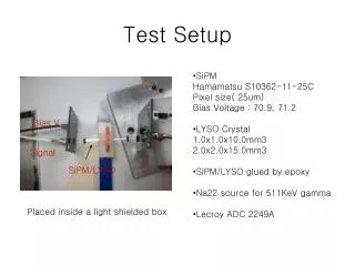
Acoustic stage: sensor • Sensor module • based on existing design • PZT5 piezoceramics plus amplifier directly coupled to steel tube • three channels per module local coincidences directional information • Power supply • cable losses use larger supply voltage ±5V generated in module
Acoustic stage: transmitter • Active element • piezoceramic transducer signals ≥ 1000 V possible • no orientation possible ring-shaped ceramic azimuthal symmetry • broad resonance large pressure amplitude • directly coupled to the ice calculable system • HV Signals • Problem: cable capacitance down in the ice • use LC-circuits sine bursts and pulses
Cables • Sensors • differential signals 3×2 (twisted pairs) • power supply 1×2 • Transmitters • signal 1×2 • power supply 1×2 • Option 1: flexible outdoor robot cable • 6×2, 8×2 … 16×2 twisted pairs • 0.51 mm2 (ATW24), 100 Ohmloss: < 2 dB/100m • used for moving parts at -40 deg • ≈ 6€ / m (8×2 one cable) • Option 2: use cheap ethernet cables • 4×2 twisted pairs • 0.52 mm2 (ATW24), 100 Ohmloss: < 2 dB/100m • two free pairs from transmitter use for auxiliary sensors • tested for -20 deg test at lower temperatures • ≈ 0.3 € / m (4×2 two cables)
String PC • Limitations • cable costs • cable losses • DAQ at top of each string • String PC • DAQ board(s) • Power supply • Fiber LAN switch • only used for data handling slow CPU, small disk • buried in snow waterproof container
String PC: DAQ • DAQ requirements • Low sampling rates • low data rates • use of the shelf DAQ • Proposal: NI-DAQ 6259 • 16 differential inputs two cards per strings • 1.25 MHz single channel • 1.0 MHz multichannel 83.3 kHz per channel • digital and analog triggering • variable gain: ± 50 mV to ± 10 V large dynamic range • 4 differential outputs transmitter signals
String PC: Power supply • Power consumption • Wire resistance: AWG24 (0.5mm2), 500m 86 ohm / pair • Sensor • ± 5V / 30mA per amplifier ~ 1W / 100mA per module • cable loss (86ohm, 0.1A) ΔU = 8.6V • Transmitter • +5V / 200mA, ~ 1W per module • cable loss (86ohm, 0.2A) ΔU = 17.2V • Power Supply: TXL Series • Uin = 86V-264 VAC 50/60Hz • size 99x82x35 mm fits into standard PC housing • sensors: TXL 035-1515D Uout = ±15V / 1.3A • transmitters: TXL Series, TXL 060-24S Uout = 24V / 2.5A • Total: ~15 W per string
Cargo cables, PCs, DAQ Sensor and transmitter modules total cargo need ≤ 5m3 Manpower deployment: trained person at the spot commissioning: DAQ connection and setup, primary testing one person, two weeks Deployment separate deployment deployment with string possible only affecting the last 400 m OMs are in safe depth find best solution with IceCube deployment responsibles Interference with IceCube Acoustic signals 1 km above IceCube < 10 mPa signal at OMs Electric signals low voltage (±5Vpp) High voltage generated localy low duty cycle (≤ 1%). DAQ, power supply seperate from IceCube no interference expected Constraints from IceCube
Summary • all components are available and tested • reasonable cost and time scale • major activities at all other neutrino telescopes • go for pole season 05/06