Low Density Parity Check (LDPC) Code Implementation
Low Density Parity Check (LDPC) Code Implementation. Matthew Pregara & Zachary Saigh Advisors: Dr. In Soo Ahn & Dr. Yufeng Lu Dept. of Electrical and Computer Eng. Contents. Background and Motivation Linear Block Coding Example Hard Decision Tanner Graph Decoding Constructing LDPC Codes

Low Density Parity Check (LDPC) Code Implementation
E N D
Presentation Transcript
Low Density Parity Check(LDPC) Code Implementation Matthew Pregara & Zachary Saigh Advisors: Dr. In Soo Ahn & Dr. Yufeng Lu Dept. of Electrical and Computer Eng.
Contents • Background and Motivation • Linear Block Coding Example • Hard Decision Tanner Graph Decoding • Constructing LDPC Codes • Soft Decision Decoding • Results • Conclusion
Background • ARQ: Automatic Repeat Request • Detects errors and requests retransmission • Example: Even or Odd Parity • FEC: Forward Error Correction • Detects AND Corrects Errors • Examples: • Linear Block Coding • Turbo Codes • Convolutional Codes
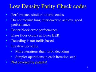
Why LDPC? • Low decoding complexity • Higher code rate • Better Error performance • Industry standard for: • 802.11n Wi-Fi • Digital Video Broadcasting • WiMAX and 4G
Performance Comparison (taken from [1])
Project Goals • Create LDPC code system simulation with MATLAB/Simulink • Implement a scaled down LDPC system on a FPGA using Xilinx System Generator • Complete System performance comparison between MATLAB/Simulink and FPGA implementation
Linear Block Coding • Block Codes are denoted by (n, k). • k = message bits (message word) • n = message bits + parity bits (coded bits) • # of parity bits: m = n - k • Code Rate R = k/n • Ex: (7,4) code • 4 message bits • +3 parity bits • = 7 coded bits • Code rate R = 4/7
Constructing Hamming Code • Factor xn +1 • Populate G matrix (k x n) with shifted factor • Take reduced row echelon form to find Systematic G matrix from G matrix • H matrix is obtained by manipulating the systematic G matrix.
Decoding S = rcvd. code word × HT
Correcting Errors • In this case the 2nd bit is corrupted • Invert the corrupted bit according to the location found by the syndrome table
Tanner Graph and Hard Decision Decoding (8,4) Example (2458) (1236) (3678) (1457)
Hard Decision Decoding Update
16 Hard Decision Decoding Update
17 17 Hard Decision Decoding Update
Differences of LDPC Code • Construct H matrix first • H is sparsely populated with 1s • Fewer edges → less computations • Find the systematic H and G matrices • G will not be sparse
Soft Decision Decoding • Uses Tanner Graph representation with an iterative process • No “hard-clipping” of received code word • 2dB performance gain over hard decision [2]
1 -7.11158 2 -1.5320 3 -0.3289 1 4 5.7602 2 5 2.7111 Load In Received Values to Variable Nodes 3 6 0.4997 4 7 -5.1652 5 8 1.5357 9 -5.0942 10 1.2526
Re-Calculate Each Edge 1 -7.11158 2 -1.5320 -1.5320 1 -0.3289 3 -0.3289 5.7602 2 5.7602 4 2.7111 5 3 0.4997 6 7 -5.1652 4 8 1.5357 9 -5.0942 5 1.2526 10
25 Re-Calculate Each Edge 1 -7.11158 -1.5320 2 -1.5320 1 -0.3289 3 -0.3289 5.7602 2 5.7602 4 2.7111 5 3 0.4997 6 7 -5.1652 4 8 1.5357 9 -5.0942 5 1.2526 10
26 26 Re-Calculate Each Edge 1 -7.11158 2 -1.5320 -1.5320 -1.5320 1 -0.3289 3 -0.3289 5.7602 5.7602 4 Update Algorithm 2 2.7111 5 0.4997 6 3 SUM 7 -5.1652 8 1.5357 4 9 -5.0942 5 1.2526 10
27 27 27 Re-Calculate Each Edge 1 -7.11158 2 -1.5320 -1.5320 -0.3289 1 -0.3289 3 -0.3289 5.7602 5.7602 4 Update Algorithm 2 2.7111 5 0.4997 6 3 SUM 7 -5.1652 8 1.5357 4 9 -5.0942 5 1.2526 10
28 28 28 Re-Calculate Each Edge 1 -7.11158 0.2096 2 -1.5320 -1.5320 5.7602 1 -0.3289 3 -0.3289 5.7602 5.7602 4 Update Algorithm 2 2.7111 5 0.4997 6 3 SUM 7 -5.1652 0.2096 8 1.5357 4 This Updated Value is Sent back to Variable Node 1 9 -5.0942 5 1.2526 10
29 Re-Calculate Each Edge 1 -7.11158 -7.11158 2 -1.5320 1 -0.3289 3 -0.3289 5.7602 2 5.7602 4 2.7111 5 3 0.4997 6 7 -5.1652 4 8 1.5357 9 -5.0942 5 1.2526 10
30 30 Re-Calculate Each Edge 1 -7.11158 -7.11158 2 -1.5320 -1.5320 1 3 -0.3289 5.7602 2 5.7602 4 2.7111 5 3 0.4997 6 7 -5.1652 4 8 1.5357 9 -5.0942 5 1.2526 10
31 31 31 Re-Calculate Each Edge 1 -7.11158 -7.11158 2 -1.5320 -1.5320 1 -0.3289 3 -0.3289 2 5.7602 4 2.7111 5 3 0.4997 6 7 -5.1652 4 8 1.5357 9 -5.0942 5 1.2526 10
Decoding Algorithm • Phi function: • Difficult to implement on a FPGA • Solutions: • Find an approximation • Construct lookup table
Lookup table Approach Note: all inputs are >=0
Conclusion • MATLAB/Simulink simulation of LDPC system has been completed. • An efficient approximation of decoding algorithm has been developed for hardware implementation. • Xilinx System generator design for the decoder has been constructed. • Comparison and verification has not been completed for those results from MATLAB and Xilinx system generator. • FPGA implementation and a scaled up system may not be completed.
References [1] Valenti, Matthew. Iterative Solutions Coded Modulation Library Theory of Operation. West Virginia University, 03 Oct. 2005. Web. 23 Oct. 2012. <www.wvu.edu>. [2] B. Sklar, Digital Communications, second edition: Fundamentals and Applications, Prentice-Hall, 2000. [3] Xilinx System Generator Manual, Xilinx Inc. , 2011.
Reducing Decoding Complexity • Square_add function: y = max_star(L1,L2) - max_star(0, L1+L2); • MAX* function: if (L1==L2) y = L1; return; end; y = max(L1,L2) + log(1+exp(-abs(L1-L2))); end;
Reducing Decoding Complexity • This: y = max(L1,L2) + log(1+exp(-abs(L1-L2))); • Becomes Approximated MAX* function: x = -abs(L1-L2); if ((x<2) && (x>=-2)) y = max(L1,L2) + 3/8; else y = max(L1,L2); end; • No costly log function
In Practice Using MATLAB’s Code Profiler… MAX* function takes: 25.85s of simulation Approx. MAX* function takes: 28.02s of equally sized simulation Difference of 2.17s
Simulation Results • (10,5) Code • 1000 codewords per datapoint, or • 10,000 bits