Car RamRod
Car RamRod. Bringing Pinball Into the Future!. Brian Arment, Ryan Hunter, Aaron Shoaf. Williams ® Touchdown. Originally Produced November of 1967 Electromechanical Solenoid and relay driven No solid-state devices Not in working order. Original Internals.


Car RamRod
E N D
Presentation Transcript
Car RamRod Bringing Pinball Into the Future! Brian Arment, Ryan Hunter, Aaron Shoaf
Williams® Touchdown • Originally Produced November of 1967 • Electromechanical • Solenoid and relay driven • No solid-state devices • Not in working order
Original Internals Relays and solenoids controlling game play Relays and solenoids controlling scoring
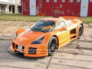
Inspiration • Newer machines use solid state devices such as those in the more modern machine at right. • We will not be mimicking the design but will use the same basic idea in modernizing our old machine.
Outline • Micro-Controller and Board • Driver/Step-up Board • Playfield Interaction • A/V Controller • Display • Audio
User Input Overview Driver Board Micro-controller Playfield 25 Vac 6 Vac A/V Controller Display Power Supply 5 VDC
User Input • Two Flipper Buttons • Start • Coin or Manual Operation • MC 14043 Quad SR Latch – De-bouncing RF CR SB LF MC 14043 4 line bus to MCU
Micro-Controller • MC68HC11 • Handles interrupts for input from sensors on playfield and users. • Controls light patterns, scoring, A/V state, game play options, game play state • Handles control of driver board for fail-safe solenoid operation.
Micro-Controller Game Option Switches MC68HC11 EPROM Sensory Input RAM A/V Controller Driver Board
Driver Board • Provides Necessary current and voltage for devices like: • Solenoids (flippers, pop-bumpers, kickers) • Lamps (in playfield and lightbox) • Nearly everything on the playboard uses it • It is controlled directly by the MPU via logic level voltages
Driver Board • Needs and Complications: • Needs to step up from 3.3-5v DC to 6 or 24v rectified AC • Make sure the flipper transistors used can handle up to 8 amps each • Need to control around 15-20 different lamp circuits • The pop-bumpers and kickout solenoids each need up to 3 amps.
Driver Board Logic-level input from MPU Pull up resistors and latches 6/24V AC Smaller BJT’s (300 mA) for the lamps Larger BJT’s (3-8 amps) for the coils To Solenoids To Lamps
Playfield (visible) • A few stipulations for the upper playfield: • Want to keep the functionality as close to the original game as possible • Want it to play a bit faster than the original (incline needs to be steeper) • Possibly implement larger flippers • Need to replace all rubber, lights • Need to touch up paint and polish the board
Playfield (underneath) • A few stipulations for the lower playfield: • All the displayed electromechanical relays are replaced by solid state via the fore-mentioned driver board • All aluminum wiring is removed and replaced with 18-20 gauge copper wiring • All contact switches are cleaned
A/V Controller • Contains two separate controllers: • DAC: • Has a file select input with data fed from the MPU • Has internal storage of uncompressed WAVE or PCM files. • DVC: • Reads the current score and points from data register • Writes to individual LED panels
A/V Controller Current Score Display Controller/Decoder -Probably an FPGA -Could also be a ROM -Can display customs graphics Score Display Points Display LED Bar Graph Play Select Audio Controller -Several sound bits stored in flash memory -A programmable ROM selects the correct track -D/A converter outputs RCA Speaker System
Display • Since this is a restoration, try to keep the scoreboard looking the same: • Replace analog score and point tumblers with individual dot-matrix digital displays • Replace mechanical football wheel with LED bar graph • Use analog lamps for “ball in play” section
Audio • Two 4 inch car speakers • Powered subwoofer • Run off of A/V controller • Speaker receives line level signal from A/V controller A/V Controller
Division of Labor • Aaron: Driver Board, Power Supply, MPU, Display, A/V controller, RAM • Brian: MPU board, A/V controller, Flash Memory, RAM, Line Bus (controllers), EPROM • Ryan: MPU, EPROM, Flash Memory, RAM, Display, Driver Board, Power Supply • All: Playfield - wiring, refurbishing, testing
Risks and Contingency Plan • A/V controller: • Implement set of beeps and bells for audio and toned down preprogrammed display art. • Cosmetic restoration • User Options • 3 or 5 ball play • #coins / credit • Free play • Multi-ball
Questions? Ask them meow!