Interfacial Mass Transfer in Gas-Liquid Reactors
100 likes | 545 Vues
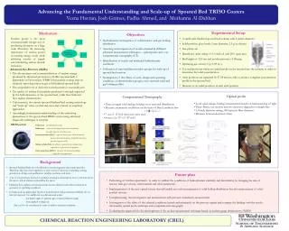
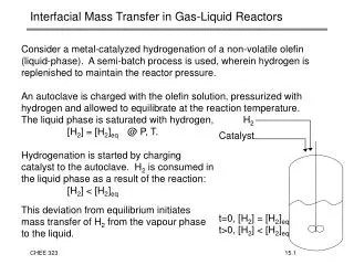
H 2 Catalyst t=0, [H 2 ] = [H 2 ] eq t>0, [H 2 ] < [H 2 ] eq. Interfacial Mass Transfer in Gas-Liquid Reactors.

Interfacial Mass Transfer in Gas-Liquid Reactors
E N D
Presentation Transcript
H2 Catalyst t=0, [H2] = [H2]eq t>0, [H2] < [H2]eq Interfacial Mass Transfer in Gas-Liquid Reactors • Consider a metal-catalyzed hydrogenation of a non-volatile olefin (liquid-phase). A semi-batch process is used, wherein hydrogen is replenished to maintain the reactor pressure. • An autoclave is charged with the olefin solution, pressurized with hydrogen and allowed to equilibrate at the reaction temperature. The liquid phase is saturated with hydrogen, [H2] = [H2]eq @ P, T. Hydrogenation is started by charging catalyst to the autoclave. H2 is consumed in the liquid phase as a result of the reaction: [H2] < [H2]eq This deviation from equilibrium initiates mass transfer of H2 from the vapour phase to the liquid.
Interfacial Mass Transfer in Gas-Liquid Reactors • Hydrogenation in a gas-liquid contactor involves: • 1. Physical adsorption of H2 across the gas-liquid interface into the • bulk liquid phase. • 2. Catalytic hydrogenation within the liquid phase. • If r1 >> r2, then the overall rate is that of the catalytic process. • Kinetic Control, [H2][H2]eq • If r1 << r2, then the rate equals the rate of interfacial mass transfer. • Mass Transfer Limited, [H2]0
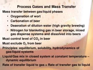
Quantifying Interfacial Mass Transfer • In all gas-liquid contactors, mass transfer takes place under forced convection, meaning the gas and liquid phases are mixed. • Physical adsorption brings the system towards an equilibrium condition. • It is known from experiment that the farther the system is from an equilibrium condition, the faster the rate of mass transfer. • Define the rate of H2 transfer across a gas-liquid interface, FH2: • where, • FH2 = interfacial transfer rate: mole/s • kl = convective mass transfer coefficient: m/s • A = gas-liquid interfacial area: m2 • [H2]* = equilibrium H2 concentration of liquid: mole/m3 • [H2] = H2 concentration of liquid: mole/m3
H2 Measuring klA in a Stirred-Tank Contactor • It is difficult to determine both kl and A by experiment, as measuring interfacial area can be tedious if not impossible in some cases. However, the product kl A is more accessible. • Mass transfer in a stirred tank can be quantified quite easily: • Equilibrate the system at low pressure under static conditions • Raise the reactor pressure several bar • At t=0, start the agitator and measure the amount of H2 required to maintain constant pressure as a function of time. 1. Equilibrate at low P [H2] = [H2]*@Plow Plow T 2. Raise P under static conditions [H2] = [H2]*@Plow Phigh T 3. Start agitator Maintain pressure [H2] [H2]*@Phigh Phigh T
Measuring klA in a Stirred-Tank Contactor • When the agitator is started, transport of H2 across the gas liquid interface commences, the rate of which is governed by: • where nH2 is the number of moles of H2 in the liquid phase. • Dividing by the volume of liquid, V, yields an expression in terms of molar concentration: • which can be integrated using the initial condition, t=0: [H2] = [H2]o to yield: • which expresses the concentration of H2 in the liquid phase as a function of time during the system’s approach towards equilibrium.
Measuring klA in a Stirred-Tank Contactor • The integrated expression for the rate of physical adsorption of H2 into a stirred solution: • fits the experimental data quite well. • The intensity of agitation, as measured by the stirring rate is seen to have a significant effect on the mass transfer rate.
Design Considerations • Whether a process operates under kinetic (chemical) control or mass transfer control depends on the rates of reaction and interfacial transfer. • If our catalytic reaction is first order with respect to hydrogen: • : mole/s m3 • and the rate of interfacial mass transfer (NH2 = FH2/V) is: • : mole/s m3 • then at steady state, these rates are equal, giving us: • or
klA/V s-1 Flow and Mixing Regimes in Gas-Liquid Reactors
Factors Influencing Mass Transfer Efficiency • Design parameters influence mass transfer efficiency by altering the convective mass transfer coefficent, kl A/V. • Factors influencing kl (film thickness, surface renewal rate) and interfacial area: • large and small-scale “mixing intensity” • liquid viscosity • gas diffusivity • Selection and design of a multi-phase reactor requires careful consideration of vessel configuration and reactant properties. • Find mass transfer data collected under conditions as close to your proposed design as possible • Be conservative in your estimates of mass transfer coefficients • Bench-scale data must be collected under kinetic control • Mass transfer effects should be handled at the pilot-scale, not bench-scale.
Heat Transfer: Design Considerations • The rate of heat removal under convective heat transfer is described as: • where, q = heat transfer rate: watts (W) • h = convective heat transfer coefficient: W/m2K • A = heat transfer area: m2 • DT = temperature difference between the surface and • the fluid : K • The heat released by hydrogenation is: • where, qrn = rate of heat generation: watts (W) • rhdgn = hydrogenation rate: mole/s • DHrn = Enthalpy of reaction: J/mole • To avoid a runaway reaction, adequate heat removal capacity (quantified by hA) must be designed into the reactor configuration.