Download
1 / 36
370 likes | 399 Vues
This engineering forum discusses the ALICE water cooling systems at the LHC detectors, outlining main problems encountered during commissioning, solutions adopted, and the organization involved. It covers the role of cooling experts, technical specifications, reviews, and updates on detector cooling performance. The forum also highlights the installation and testing processes, including the complex cooling circuits and heat screens of the TPC. Furthermore, it addresses safety measures, leakless operation, and commissioning stages for maintaining efficient cooling services across the detectors.

E N D
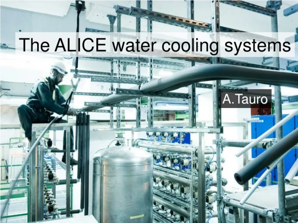
The ALICE water cooling systems A.Tauro Engineering Forum on Cooling for the LHC Detectors
Outline • ALICE cooling organization • Overview of the ALICE water cooling systems • Main problems found during the commissioning of the detectors • TPC • ITS • Solutions adopted case by case • Conclusions Engineering Forum on Cooling for the LHC Detectors
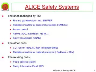
ALICE cooling organization • Cooling coordinator: • Provides the interface between the cooling experts/TS-CV/external companies and the technical coordination (TC) • Responsible for the installation and testing of cooling services • Follows the commissioning stages • Sub-detector cooling experts: • Provide technical specifications • Perform prototyping and/or mock-up tests • Commission the final system • TS-CV/DC: • In charge of the fabrication, installation, operation and commissioning of the cooling plants TC Cooling coordinator TS-CV/DC Detector expts CERN techs or ext comp Detector expts Detector expts Cooling plant Cooling services Cooling plant Cooling services Cooling services Cooling plant Engineering Forum on Cooling for the LHC Detectors
Updates and reviews • Regular status updates: • Installation -> weekly planning meetings • Commissioning -> daily commissioning meetings • Technical board and technical forum • Cooling reviews dedicated to each sub-detector aiming at discussing: • Detector protection and safety (interlocks, HW protections, relief valves,…) • Cooling performances • In case of problems -> engineering change requests (re-routing of lines, cooling plant modifications) Engineering Forum on Cooling for the LHC Detectors
Example: ALICE TB June ‘08 Engineering Forum on Cooling for the LHC Detectors
Example: ALICE TF Oct ‘07 Engineering Forum on Cooling for the LHC Detectors
The ALICE experiment Central detectors forward muonspectrometer Engineering Forum on Cooling for the LHC Detectors
The L3 magnet in 2006… Engineering Forum on Cooling for the LHC Detectors
ALICE front view Engineering Forum on Cooling for the LHC Detectors
…and how it looks like now Engineering Forum on Cooling for the LHC Detectors
Location of the cooling plants in the UX25 cavern TOF, EMC, CPV, PHOS TRD PHOS HMPID TPC SPD SSD & SDD Engineering Forum on Cooling for the LHC Detectors
Services through the L3 door Engineering Forum on Cooling for the LHC Detectors
Installation of pipes in the ALICE cavern Installation: 1 and ½ year, 7 teams, ~20’000 mt of pipes (40% stainless steel), ~3700 press fittings Test: about 500 over-pressure tests (~3’400hrs in total) Engineering Forum on Cooling for the LHC Detectors
ALICE cooling plants Cooling plants: • 7 units (5 water, 2 evaporative). Most of them are shared between detectors • 5 produced by TS/CV-DC, 2 outsourced (Italy, Russia) • PHOS is the only -25°C, all the others work at +16,+18°C • Leakless operation • First unit (SPD) delivered beginning 2006, last one (PHOS) beginning 2008 • Total value of cooling plants >1MCHF Engineering Forum on Cooling for the LHC Detectors
The leakless operation ΔPdetector Pout Pin < Patm It works only if Pin < Patm Not all the loop is under-pressure!!! ΔPdetector vs flow must be known ΔPreturn should be calculated ΔP return ΔP supply h Ptank Ppump Engineering Forum on Cooling for the LHC Detectors Jose Direito TS/CV/DC, 13.05.2008
The TPC cooling Engineering Forum on Cooling for the LHC Detectors
Temperature uniformity across the TPC volume • Ne/CO2 is a ‘cold’ gas, with a steep dependence of drift velocity on temperature • Uniformity of the temperature field must be extremely good (ΔT ≤ 0.1 K) • 18x2 trapezoidal read-out chambers each one consuming 720W • Complex system of heat screens and cooling circuits • Heat screens: • outer radius toward the TRD • inner radius shielding from the ITS services • readout chamber bodies shielding from the FEE heat dissipation • FEE towards the outside • Cooling circuits: • resistive potential dividers • front-end electronics Engineering Forum on Cooling for the LHC Detectors
0.5 mm copper tubes connected to 3 mm Si-tubes, without clamp or bracket Connection tested to withstand > 2 bar overpressure. But… … it could happen that the pipes are not properly plugged after an intervention for which they have to be disconnected -> what happen if one hose become disconnected ? Front end electronics cooling pipes Engineering Forum on Cooling for the LHC Detectors
Test with dummy sector • Test with dummy sector done in 2007 in the UX25 cavern • Demonstrates that if a Si-pipe bunches-off there is a leak inside the chamber • The plant takes 40s from the leak before stopping the water circulation • -> P sensors installed on each chamber input line • Continuous monitoring of pressures to verify underpressure operation • Exceeding the threshold would immediately trigger an ALARM and stop circulation 40 s Engineering Forum on Cooling for the LHC Detectors
Increasing the tank pressure solves the problem but then makes the startup impossible Startup: need to kick up the pressure in order to get rid of the air in the pipe Solution: switch from startup tank pressure (e.g. 350 mbar) to running mode (e.g. 500 mbar) Pthreshold “Cavitation” problem • For some sectors it has been observed ad audible noise coming from the pipes • These sectors exhibited a Pout < 50 mbar • “Cavitation”, potentially dangerous condition. Increase of the flow resistance due to bi-phase liquid Engineering Forum on Cooling for the LHC Detectors
sectors with new routing Routing of cooling lines Siphons in lines • In some sectors there was no flow • The reason was the presence of important siphons in the lines • These lines have been re-routed • After re-routing of these lines the problem was solved pressure sensor threshold Engineering Forum on Cooling for the LHC Detectors
Re-routing of TPC lines New lines installed Engineering Forum on Cooling for the LHC Detectors
ROC temperatures Engineering Forum on Cooling for the LHC Detectors
Skirt temperatures Engineering Forum on Cooling for the LHC Detectors
The laser system is used for precise position inter-calibration for the readout chambers and allows online monitoring of temperature and space-charge distortions, both of the order of a few mm Engineering Forum on Cooling for the LHC Detectors
The ITS cooling Engineering Forum on Cooling for the LHC Detectors
Layout of the ITS • Only SPD uses C4F10 coolant • low material budget, long-term stability against corrosion, chemical compatibility, minimal temperature gradients, cooling duct temperature above the dew point • SDD and SSD share the same (water) cooling plant • ITS uses stainless steel pipes Engineering Forum on Cooling for the LHC Detectors
Extensive (2 years) pre-commissioning in the lab In normal operation, if a sudden failure of the cooling were to occur, the temperature at the module would increase at a rate of 1 °C/s Continuous monitoring and a fast, reliable safety interlock on each module are therefore mandatory DCS and interlocks also tested in the lab Problems encountered in real installation Low or zero flow in some loops. Due to different pipe layout with respect to lab Still some liquid back into compressor. Heaters added SPD commissioning Engineering Forum on Cooling for the LHC Detectors
The SSD cooling Two thin (40 μm wall thickness) phynox tubes Engineering Forum on Cooling for the LHC Detectors
The SSD FEE chips Engineering Forum on Cooling for the LHC Detectors
Cleaning of the lines. June ‘07 • In June 2007, before connecting the ITS to the cooling plant the pipes were cleaned by circulating water • Found metal chips, dust particles which could have damaged the detector • Water circulation continued for several days • Filters of different mesh replaced at every time • -> lesson learnt: use extreme care during pipe installation. Plug them before connecting the detector 150um filter 50um filter Engineering Forum on Cooling for the LHC Detectors
Water leak. July ‘07 • In July 2007, after 2 days of run with the nominal flow, a water leak was detected inside the ITS barrel (probably due to an open in the SDD region) • Mylar foil acted as drain, water level not high enough to reach ladders • In order to be leak proof, it was then decided to allow to work only in sub-atmospheric region inside the detector • As for the TPC, pressure sensors were introduced in order to read the pressures at the detector Engineering Forum on Cooling for the LHC Detectors
Problems and solutions • When lowering the tank pressure to be underpressure at the detector, the “cavitation” problem appeared • Solution: 1) re-routing of some lines, 2) changing the inner pipe diameter • Given the different routing of the lines, the flows amongst the loops were not equalized • Solution (SDD): upgrade the plant with flowmeters and pressure regulators • Solution (SSD): install balancing valves on input-output lines • SSD and SDD have different flows and different ΔPdetector -> each one found an optimum value for Ptank and Ppump • Solution: install back-pressure regulators (SSD) + input pressure regulator (SSD) to decouple as much as possible the two systems • The loops were difficult to drain • Solution: install bypass into cooling plant and manual valves in each line Engineering Forum on Cooling for the LHC Detectors
The new lines Add 5 lines 16/18 Add 5 lines 16/18 Add 3+2 lines 16/18 Add 3 lines 16/18 till here Cost: 50KCHF Engineering Forum on Cooling for the LHC Detectors Add 2 lines 16/18 till here
Pressure regulators for SDD Flowmeters for SDD Manual valves on all SSD returns and supplies 5 enlarged return valves+ forks for the 18mm OD SDD pipes By-passes for Circuit Draining Pressure regulator for the SSD Two actuated valves on the common returns with remote positioning control to decouple return pressure from the SDD The SSD-SDD plant upgrade Cost of the upgrade: 150KCHF Engineering Forum on Cooling for the LHC Detectors
Conclusions • The ALICE cooling organization has been described. The cooling coordinator acting as a reference for all the cooling matters • The leakless operation is effective only if Pin<Patm and it doesn’t guarantee that there are no leaks • P sensors are fundamental in leakless systems. They should be part of the design of the cooling system • It is fundamental to measure ΔPdetector vs flow and to have a good estimate of ΔPreturn. Piping inside the detector must be robust • An optimized routing of the lines is crucial to minimize the impedance and to avoid siphons. Max care must be taken in the cleaning procedures • Test testtest is always the key Engineering Forum on Cooling for the LHC Detectors